Red Light, Green Light

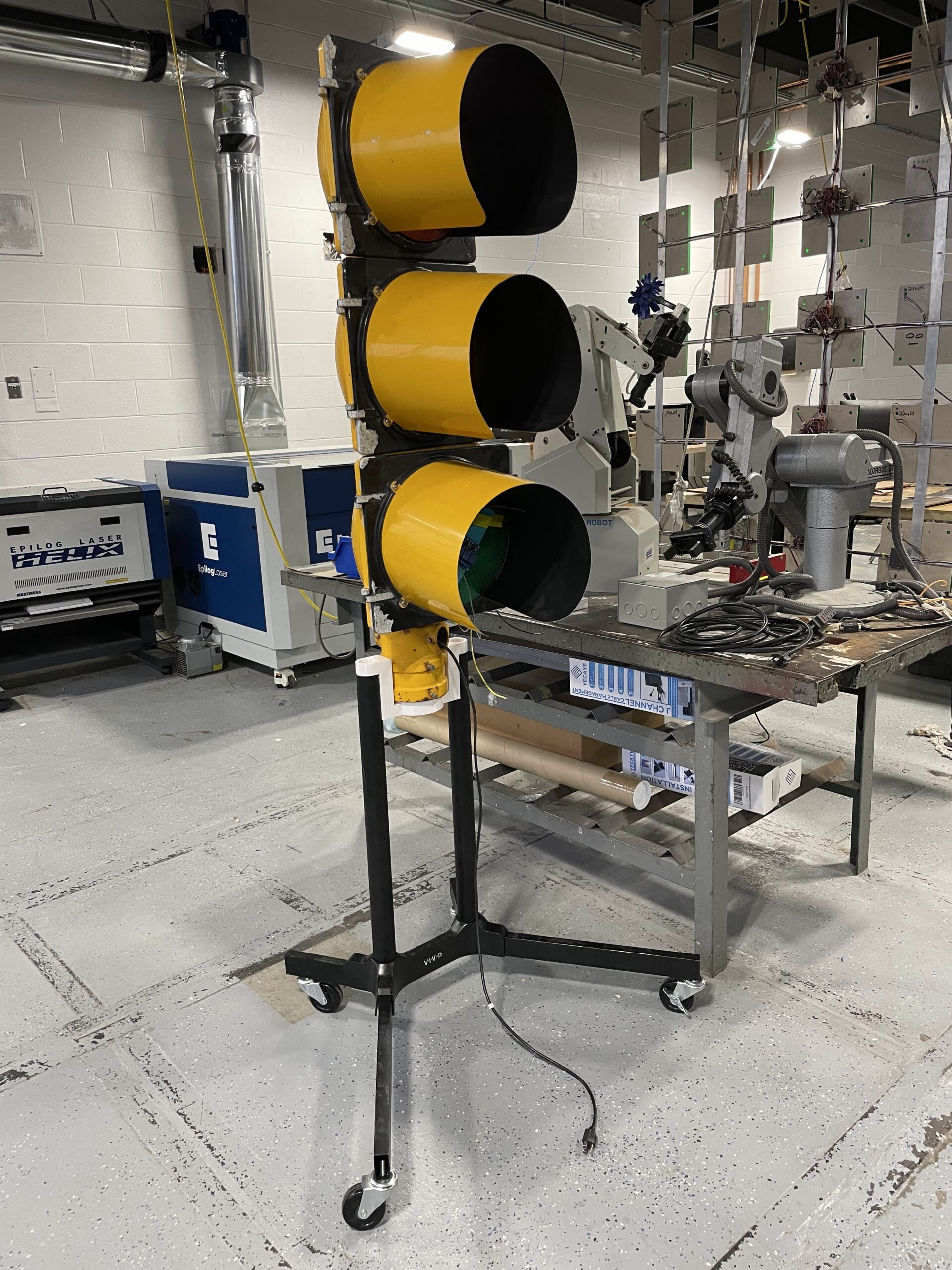
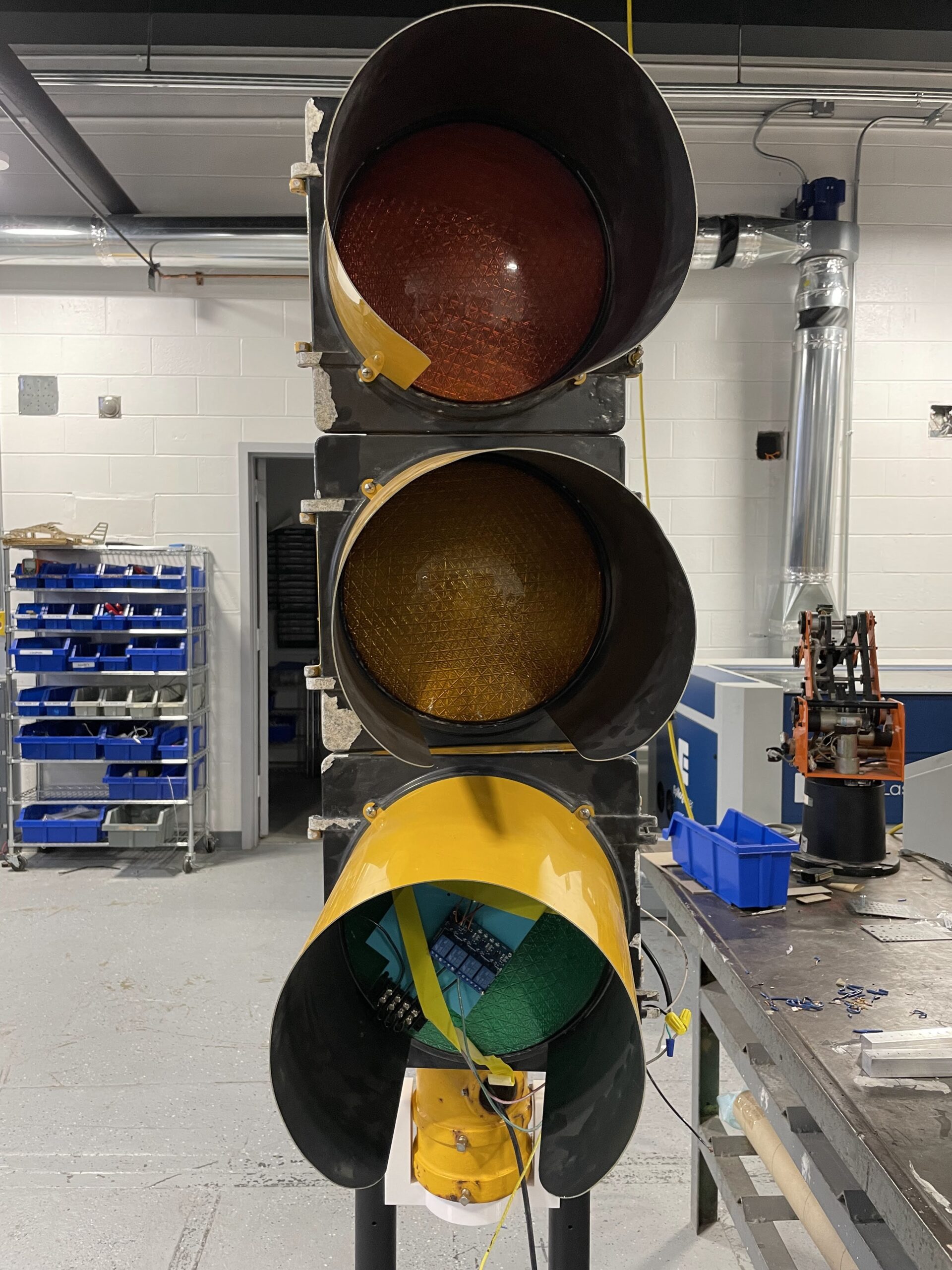
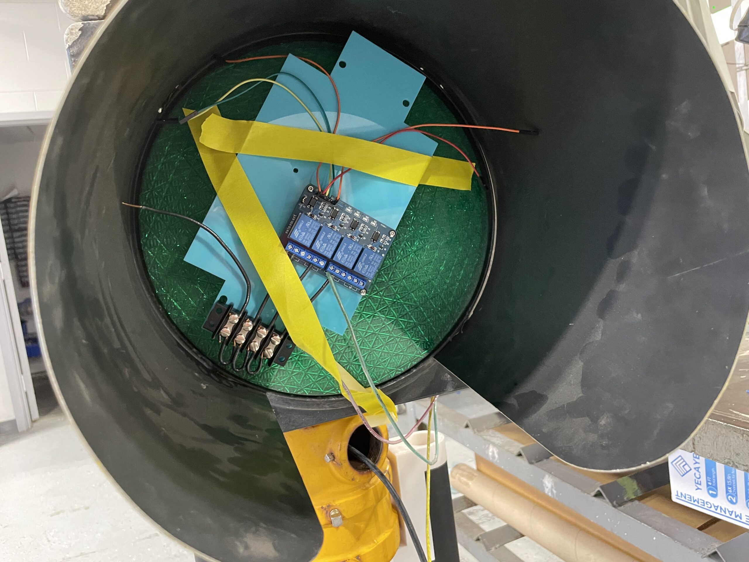
Junior student Clark B has been working on circuitry to control an actual Stop Light that was donated to the shop a few years ago. Many students had thought about working on a project with the Stop Light, but nobody truly took on the project as Clark has done. So far he has written a program for an Arduino that will allow the light to turn on to reflect the daily class schedule. Green light for when we are in class time, yellow for 5 minutes before the bell, and red for time between classes. Along with his Arduino, he has a relay to control the AC voltage that turns on the light.

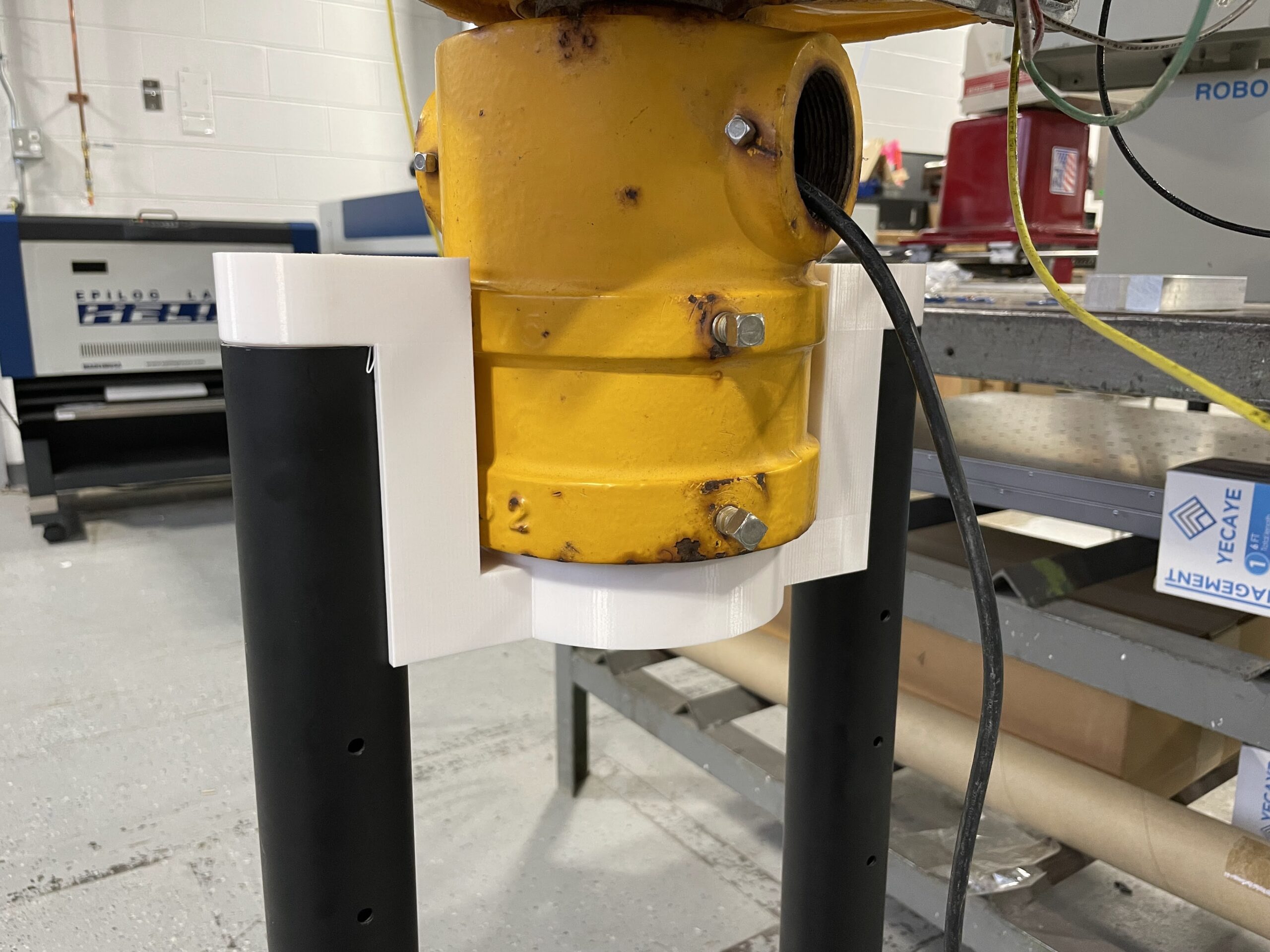
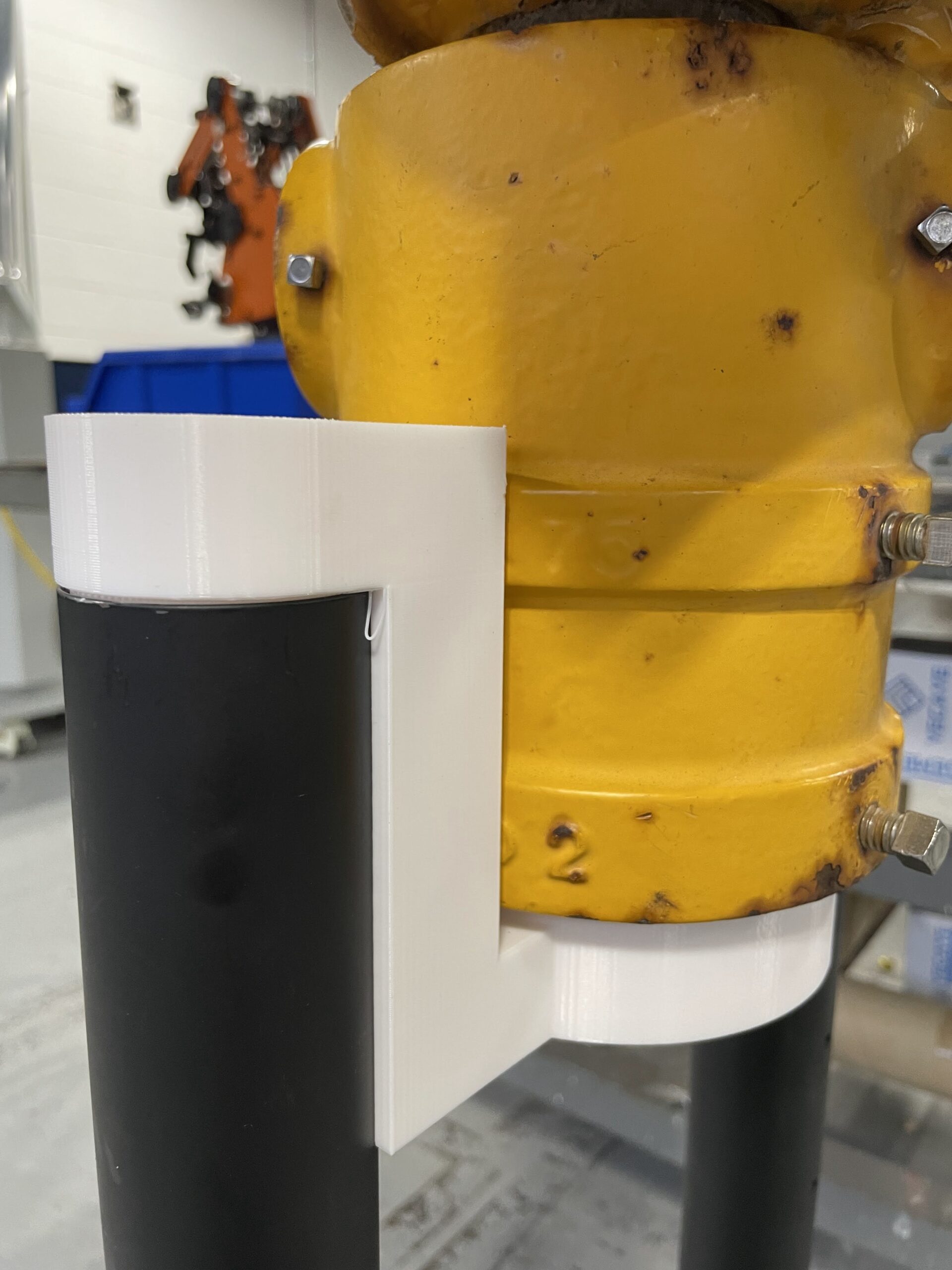
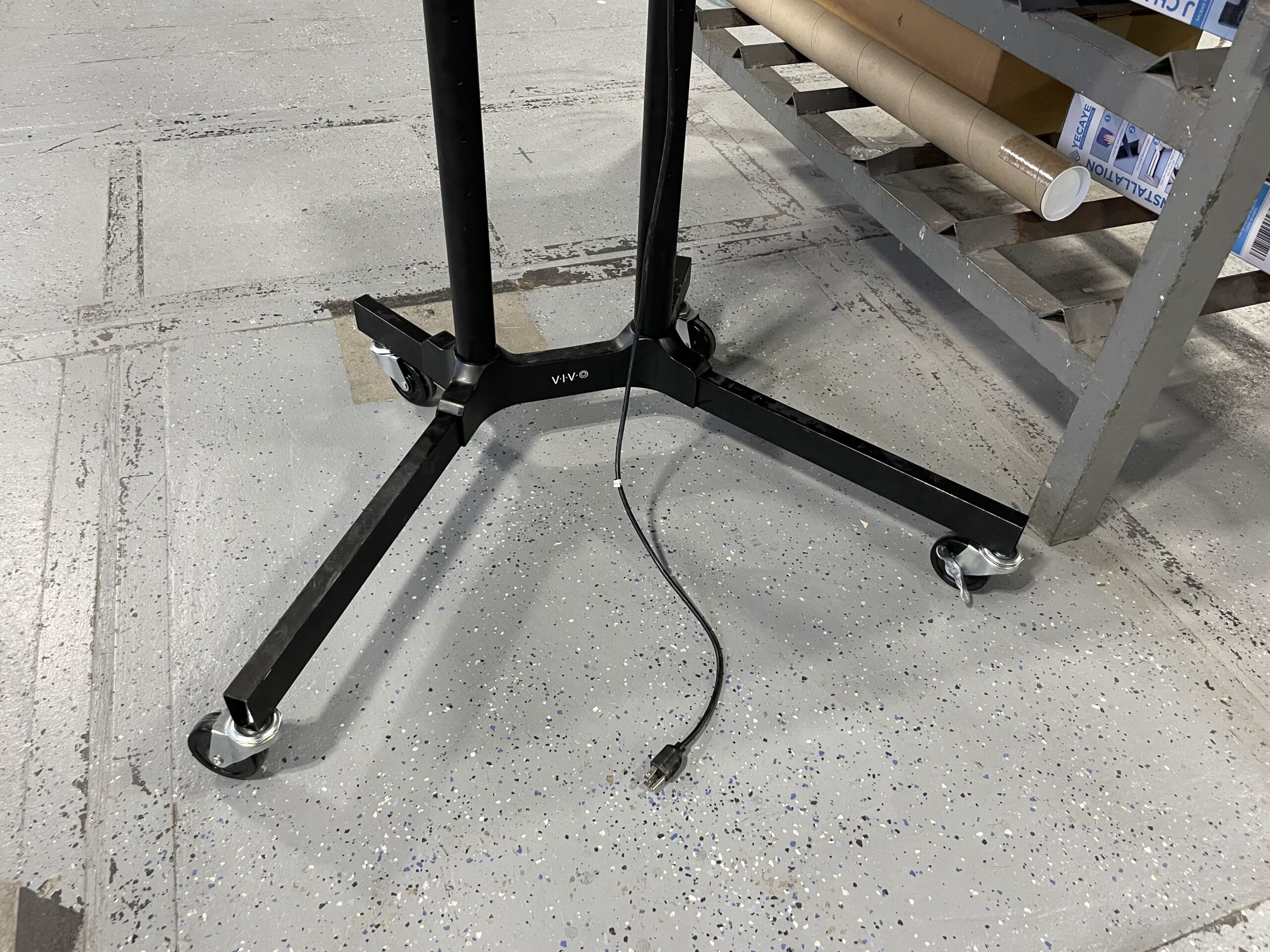
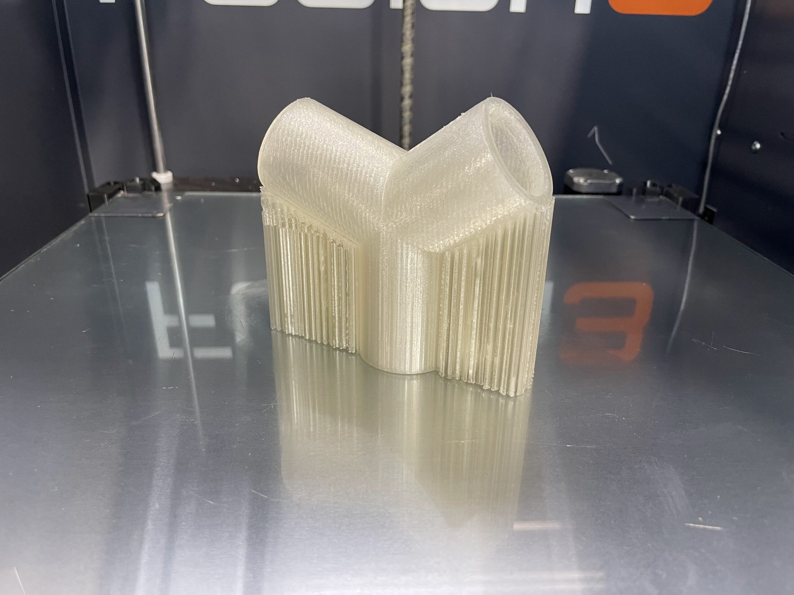
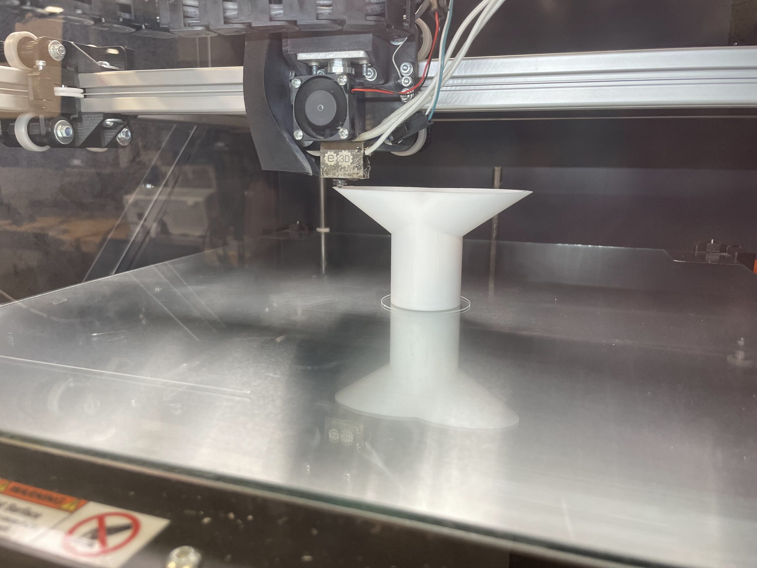
Additionally, we repurposed an old rolling television stand that was being dumped in the trash. The wheels were broken so we drilled new holes in the steel frame, tapped the holes for M10 bolts, and used some new casters we had in our storage room. To connect the light to the stand, another student, Senior Daniel R, 3D modeled and printed a connecting element that rests on the poles of the TV stand, and allows the Stop Light to slip onto the top of the connector. It’s coming together very well at the moment, and just a little more wiring and finalizing the coding should complete the project. Will post again when completed. For now, some photos below.

Support

It’s been a few days since my last post, was a bit derailed from the February break here at school among other things. Over the weekend, a student had started a 3D print of a Y shaped connector for our dust collecting system for our 2 Bantam PCB Mills. It was printed upright with support for the legs that make the top part of the Y. I’m not always available when students begin a 3D print, and most have my permission to print without me needing to micromanage their files and how they get sent to the printer. One thing I do try to instill in my students, however, is understanding how a CAD object will be manufactured before they even begin working on the computer. That is, they should know whether or not they are going to 3D print, lasercut, or mill that part because that has ramifications as to how the part should be created in Fusion 360. Below you will see the print I saw when I arrived at school on Monday morning.

Now, there is nothing wrong with this print – it actually came out quite nice. Yet, our 3D printers have the capability to print angles up to 45 degrees without support. Which means this print could be printed without the support structures – which saves us not only filament but also time. I corrected the file in Simplify3D and reprinted it to demonstrate to students the advantages of understanding their method of manufacturing in order to model more appropriately.

There is nothing wrong with this student’s model, and it printed out fine without support. We try and teach students, especially with 3D printing, to try to design without the need for support in order to save time and material. Below is a quick video the the printer managing the overhangs in this print.

Camp Mustang

Today I needed to work on a lasercut project for the Camp Mustang that will be happening next week at the high school. Camp Mustang is a 2 day in school event for elementary and secondary school students within the Medford school district. I will be offering students CAD lessons, lasercutting, and some basic electronics. Several years ago, at my previous teaching job, I created a lasercut bug that could be assembled and then an LED and battery press fit into it so it lit up. I’ve created something similar for students but more of a robot shape. I’m still waiting on some material to cut each one out on, hoping that arrives today – otherwise I will be rushing around next week to get these cut for the students to assemble. For now, you can see the image that is used to lasercut on our Epilog Fusion Pro lasercutter.

Pi Radio Internals

Just a quick update on the Pi Radio. I have been working on the internals and am close to having some nice acrylic mounting panels for the interior of the radio. Additionally, I have chosen a speaker to use, which will replace the old damaged speaker that was in the unit when it was purchased. The new speaker is a 4″ Dayton Audio DMA105 8 ohm, which is also being used by another student for a speaker project they are working on. Will post more on that project once it is further along. My radio needs a few more adjustments to the CAD model, and a couple of more test fits before we can wire it up and test my co-teacher’s coding with the Raspberry Pi. A few photos below showing the updated components inside the radio housing.

Pi Radio – It’s Alive

I had mentioned the Pi Radio project to my co-teacher and he was pretty enthusiastic about working on it. Since he is the coding expert, I decided to let him work out those specifics, while I work on the CAD aspects and building the project once the electronic portion is complete. Today he successfully coded the Raspberry Pi to tune to different internet radio stations using a rotary encoder, which will mimic using the tuner from the radio to ‘tune’ to different stations. Additionally, he has incorporated a second rotary encoder for volume control. Everything seems to be working now, but still some work finalizing the code and electronics.

For my part, I’ve started putting the entire radio into CAD in order to make all the new interior components to hold the new electronics. I’ve finally finished recreating the outer housing, and took a quick photo to show how well it came out. Looks just like the real thing. Next, I need to create some new components for lasercutting and 3D printing.