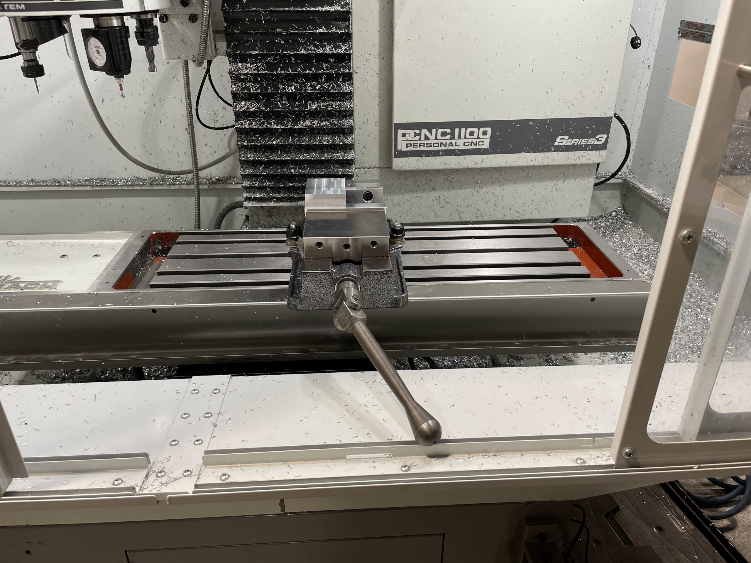
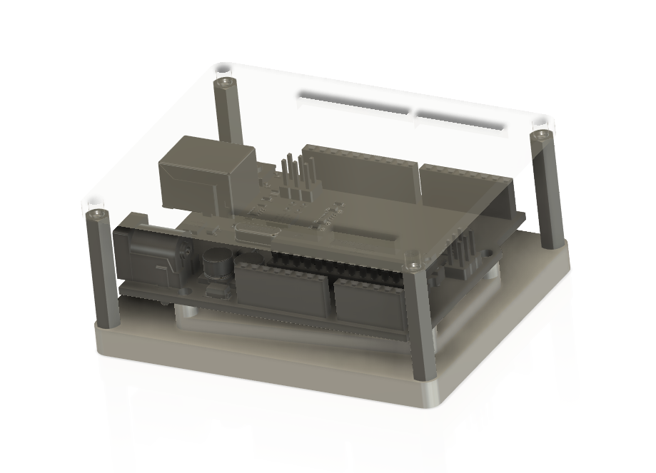
Today I’ll talk a little bit about setting up a part for use on our Tormach PCNC 1100 mill. As I said in a previous post, I’m working on a new project for students, creating a custom arduino holder out of aluminum. I’ve been documenting the process of preparing the stock for the mill.
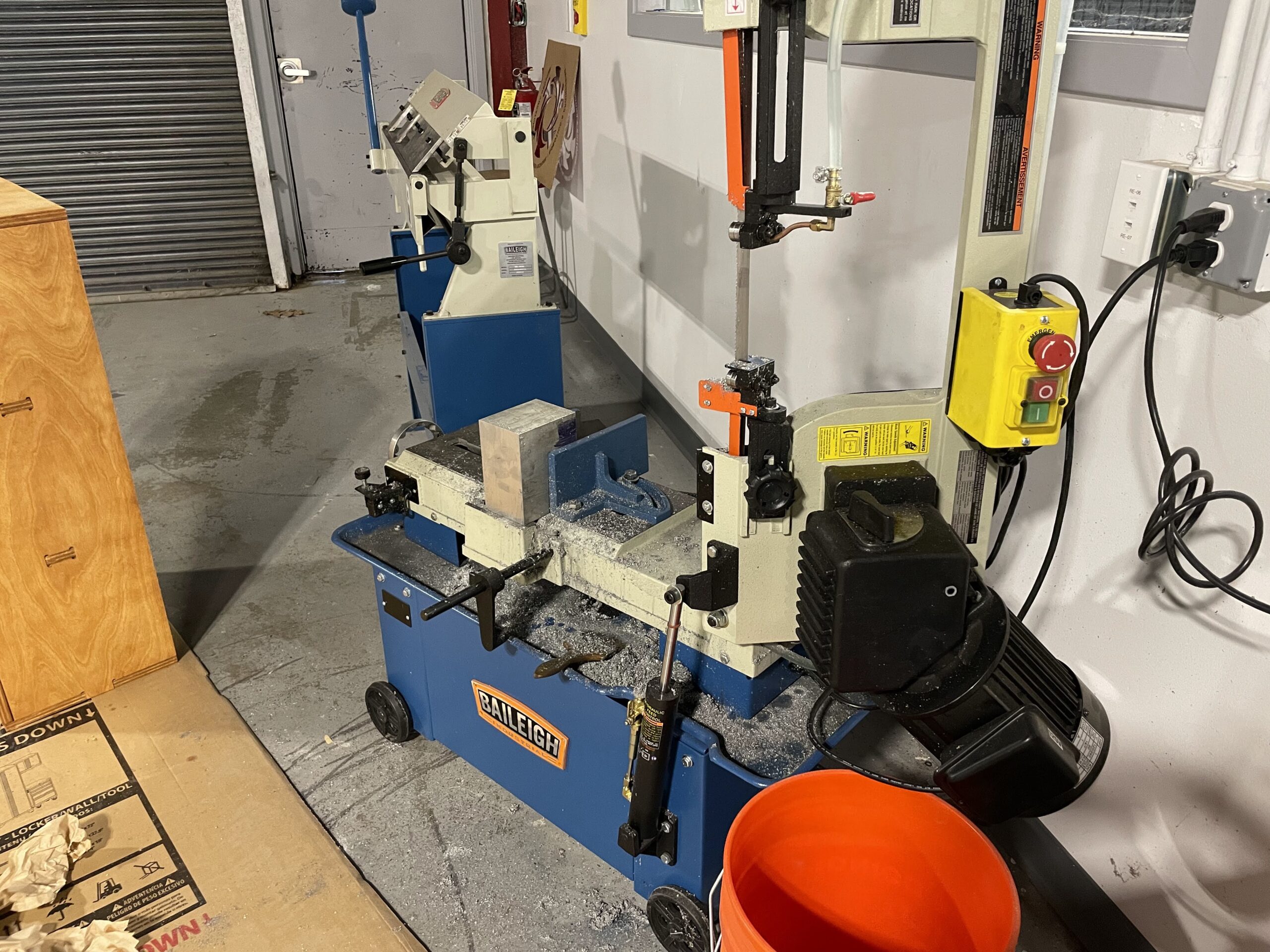
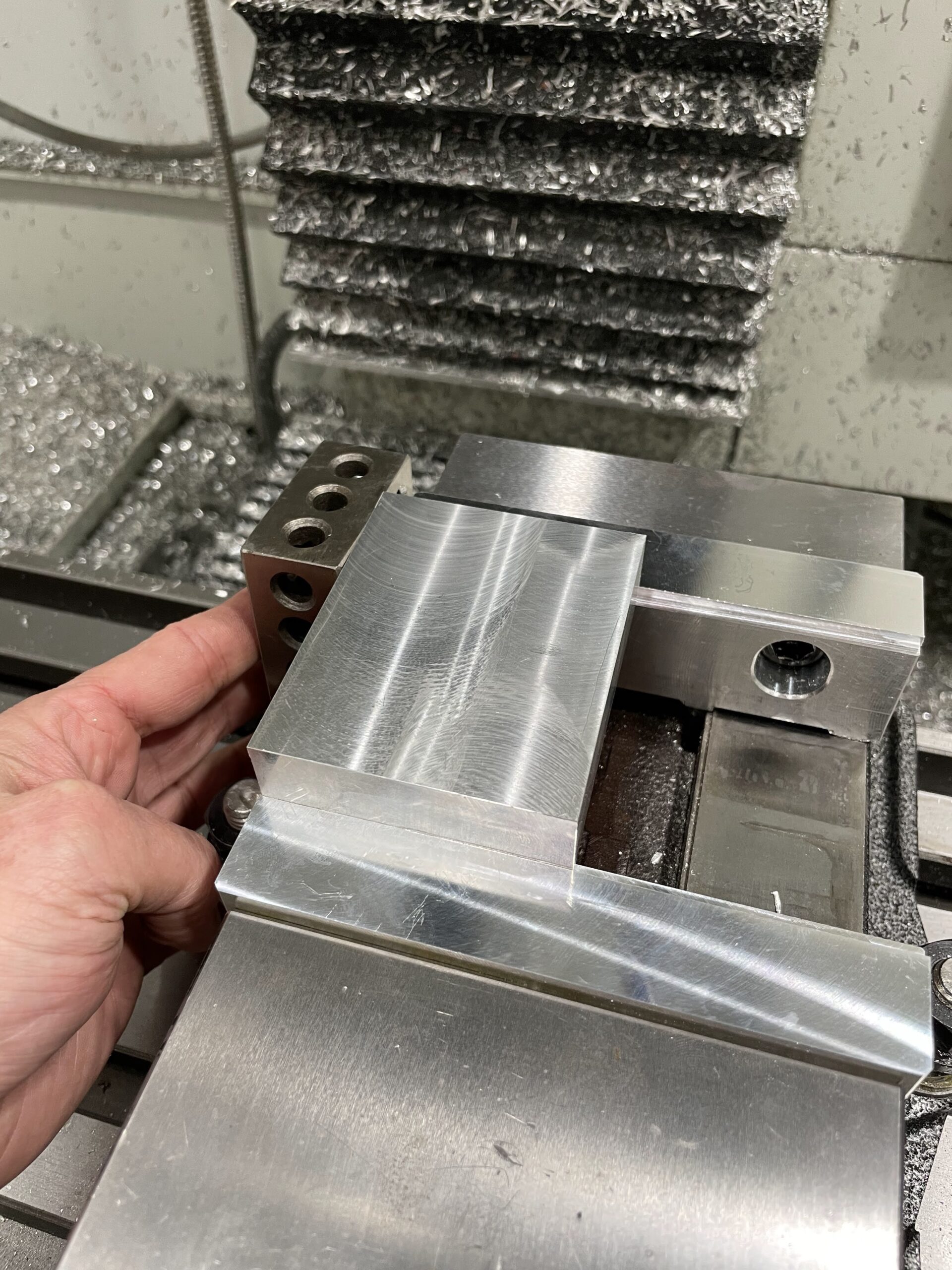
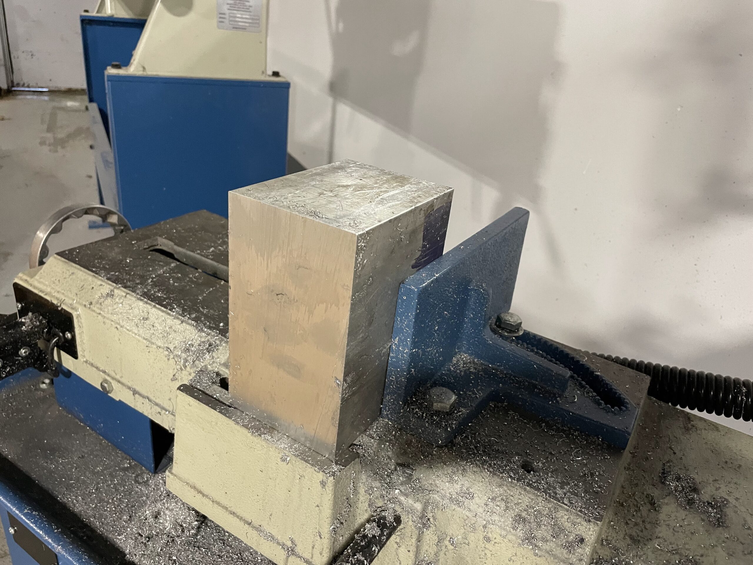
The project as designed in CAD calls for a 0.8 x 2.6 x 3.2 in block of aluminum stock. I’ve cut a .9″ thick piece of stock from a 6 x 4 inch block and then roughed it to down on the bandsaw to get it close to the dimensions I want. Next, I took it over to our Trax mill and faced off all sides until it was milled to the dimensions mentioned above. I probably do not need to be this precise, but its a good exercise, and will give the students a good beginning in using our manual mills.
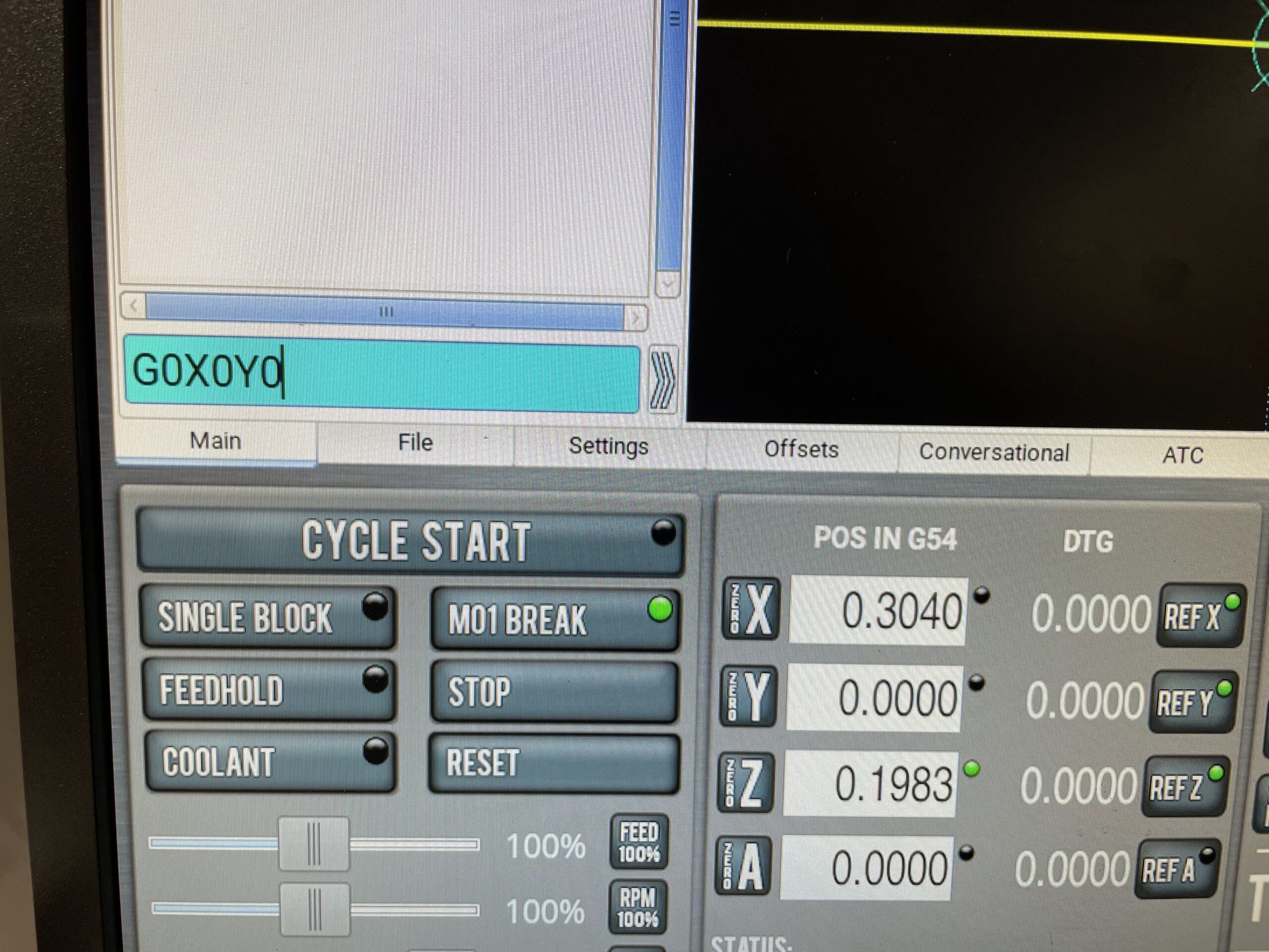
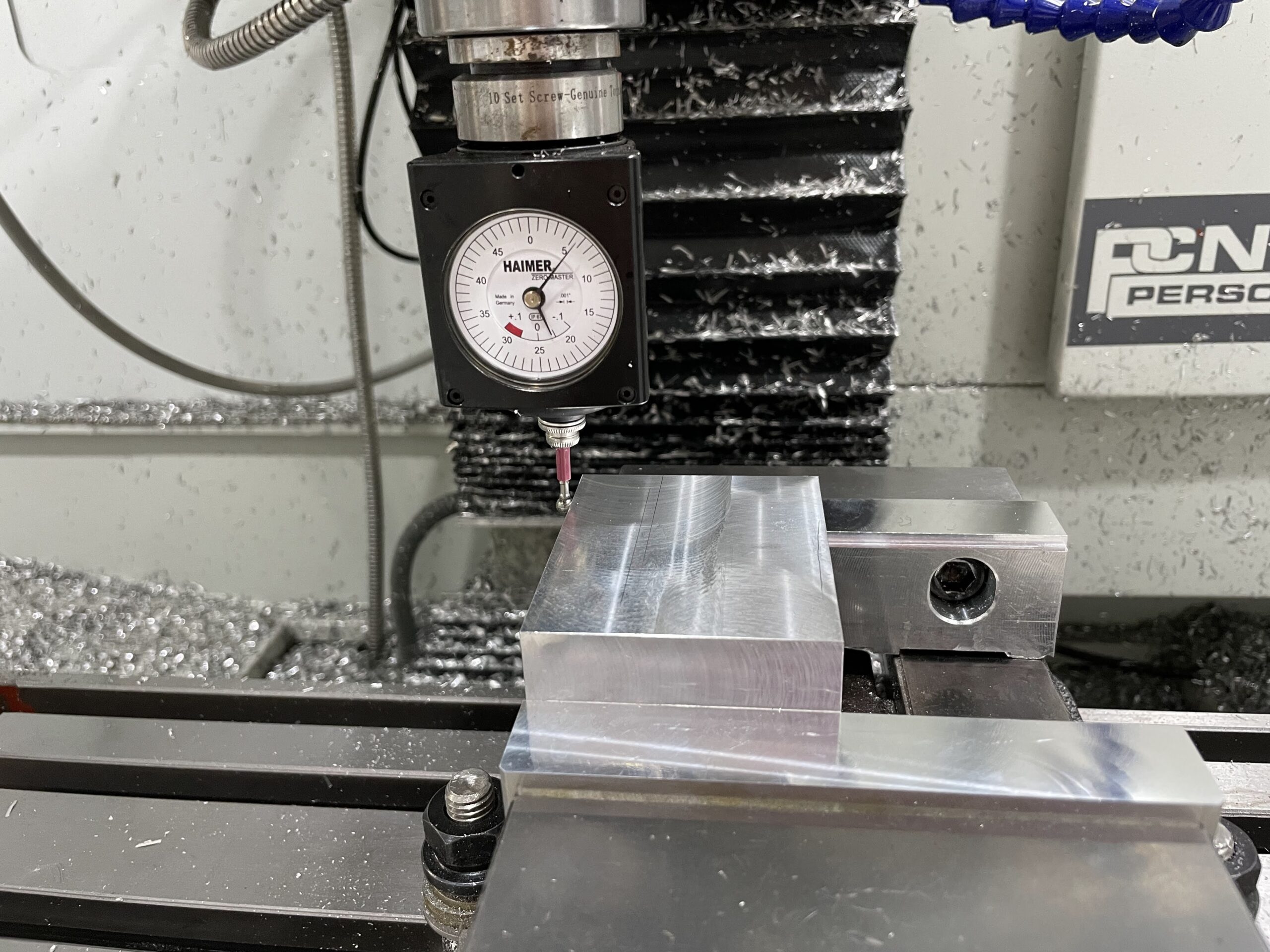
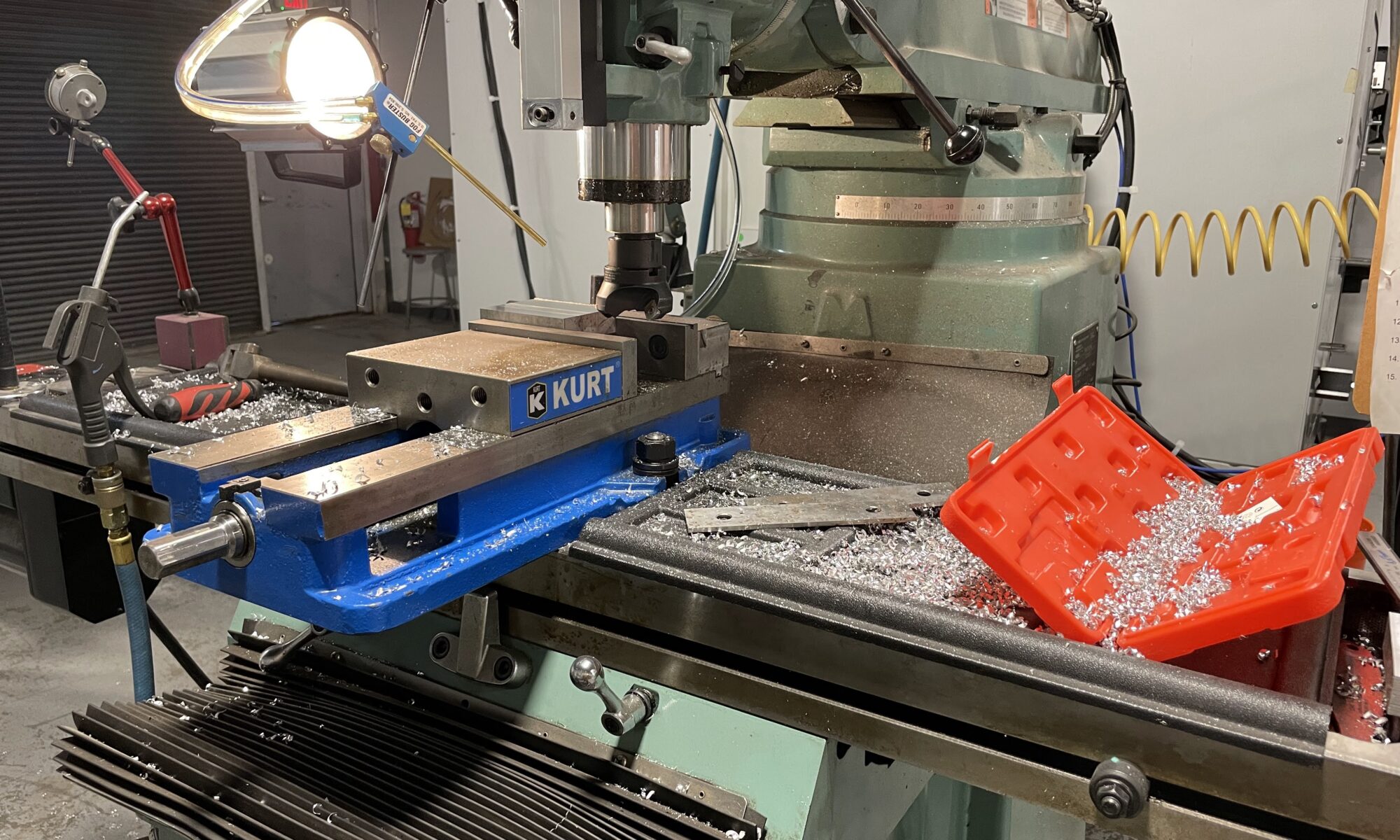
Once the block was ready I took it over to our Tormach machine and proceeded to zero out the X, Y, and Z coordinates. This is extremely easy using the Heimer – a measuring tool that provides the zero, or edge, coordinate without the user needing to to any math as might be done with a standard edge finder. See video below.
This project requires a part flip, and for the first attempt, I tried using the same X and Y coordinates – which did not work out. Mostly because the Y coordinates did not match on the flip. Another issue I had was tapping the holes. I did not properly set the RPM and feedrate correctly for the 4-40 tap, and it broke immediately. A silly mistake, but one that will be easily fixed next time I run the job.
There are some photos and videos below of the process, although I forgot to take a photo of the finished product. Will update on the project next week.