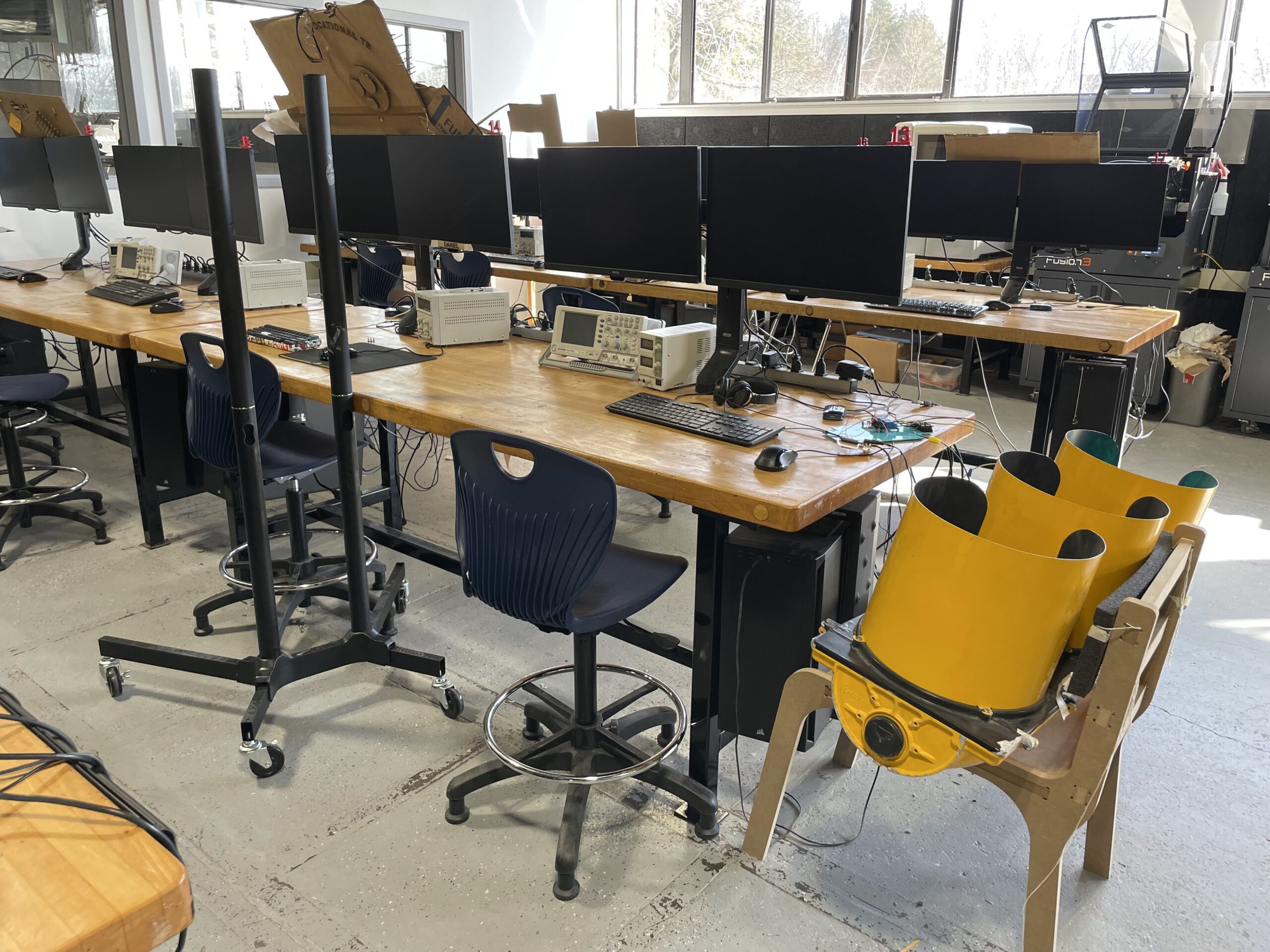
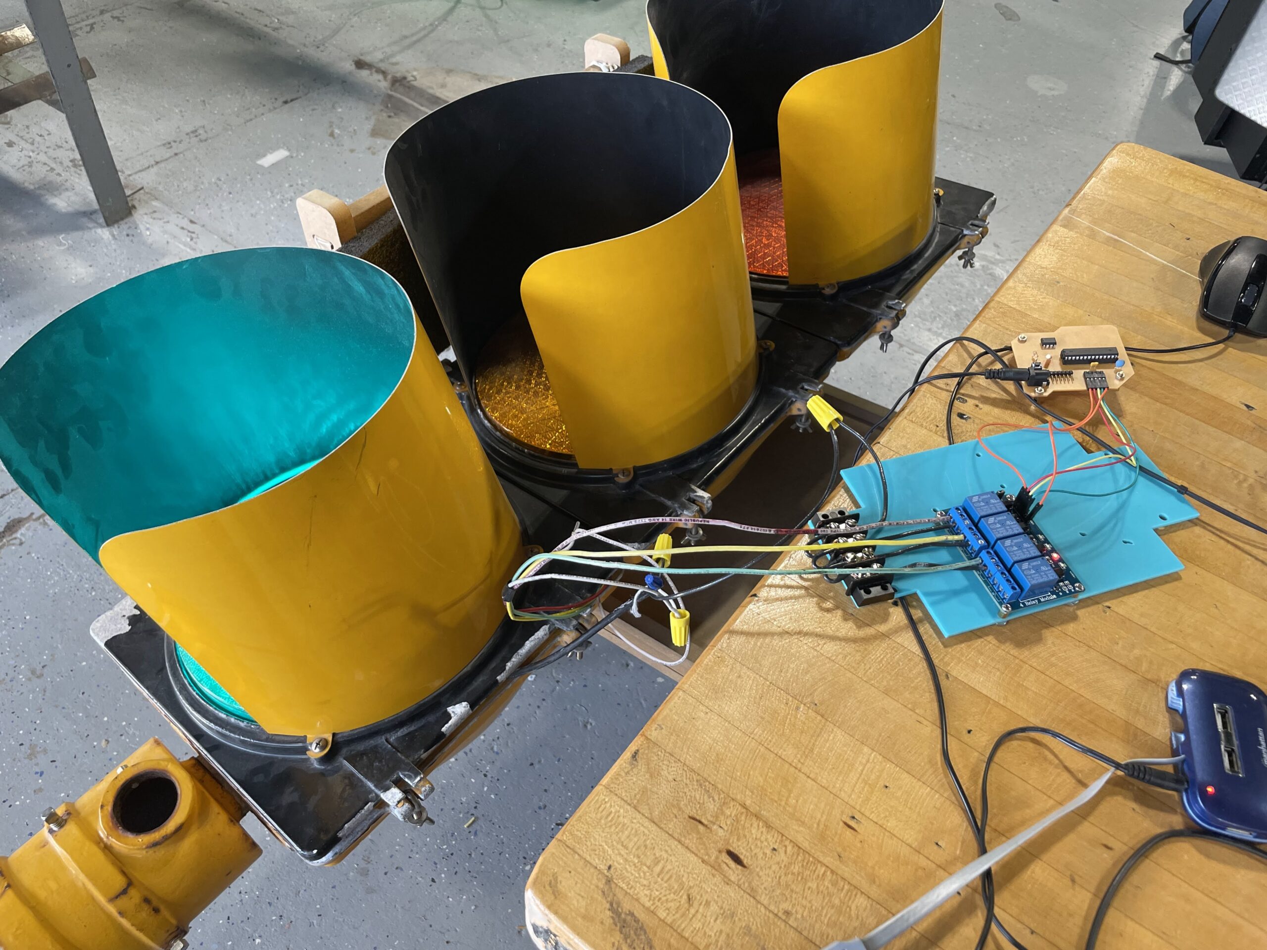
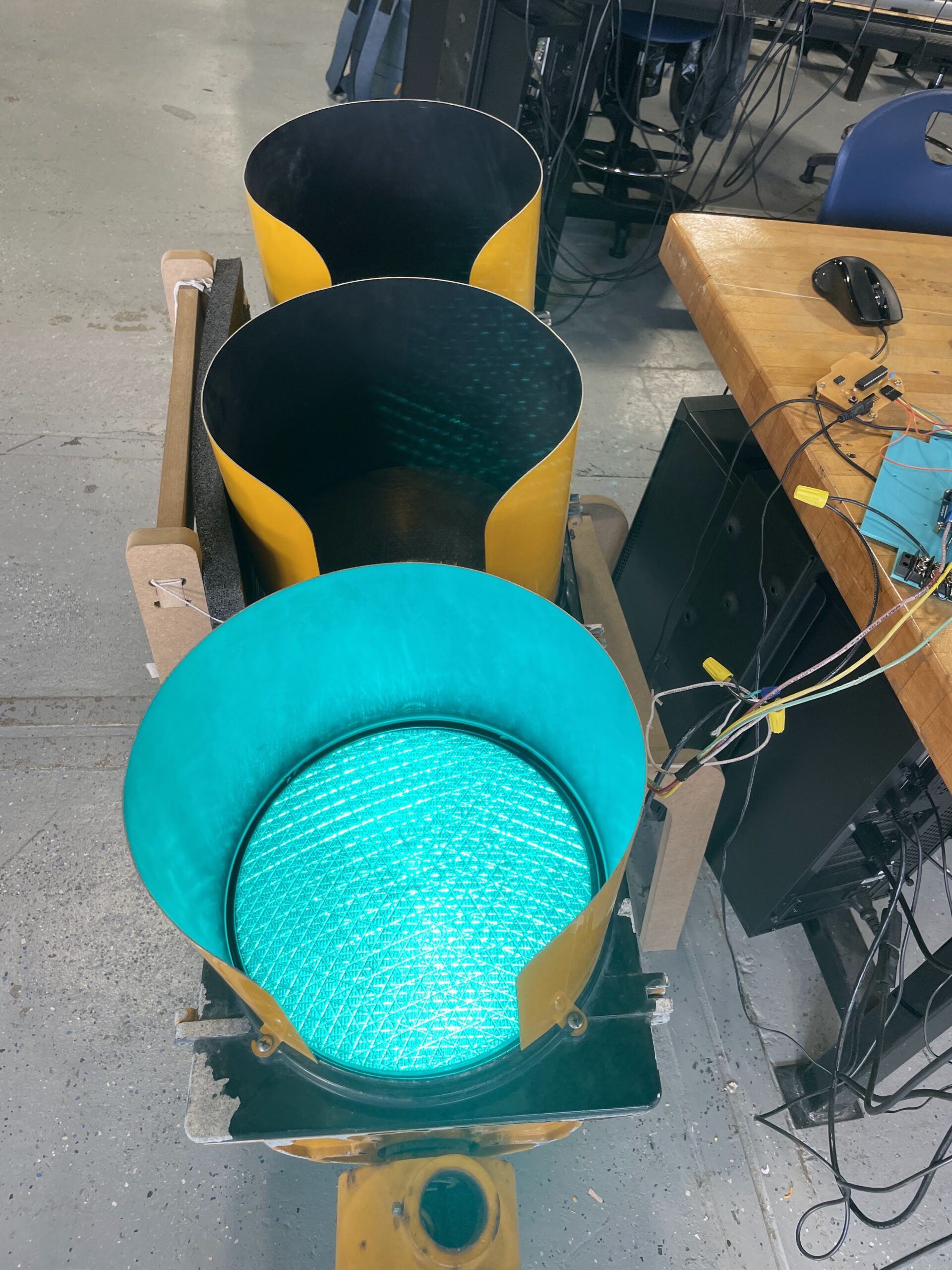
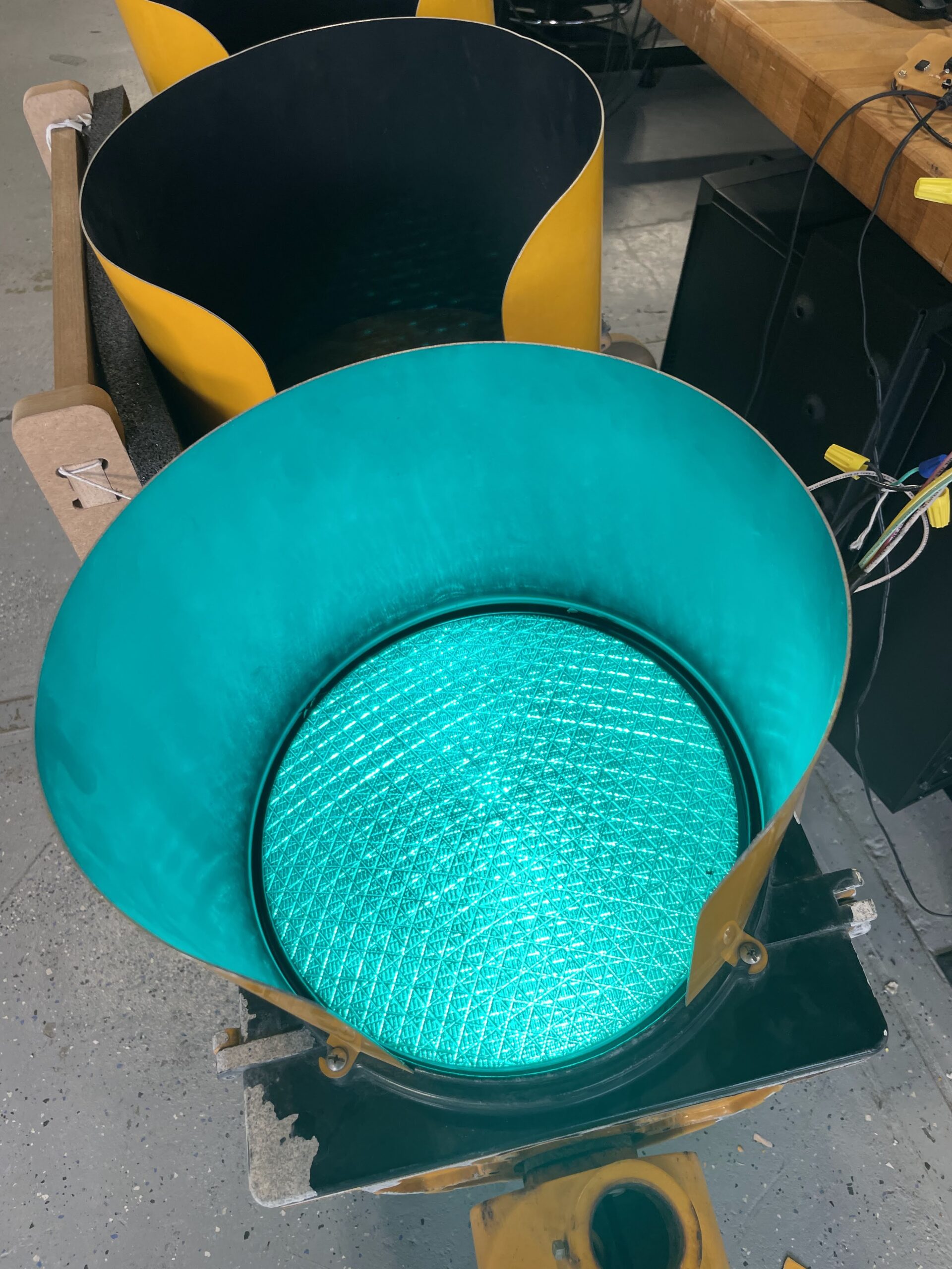
The Stop Light project continues with Junior Clark B. ’23 working fastidiously each day. Clark had the code working on a breadboard, and has spent time using Eagle to create a custom PCB on our Bantam Tools PCB mill. The process of learning how to create a pcb in a CAD/CAM software such as Eagle is very difficult, so kudos to Clark for working through it. As we have found, however, the first attempt at creating a board is usually not the final board – as it tends to take a few efforts before the final working prototype is complete.
When the pcb was coupled together with the relay for high voltage and the light, everything turns on, just now exactly when we want it to. There is probably an error in the code, so Clark needs to spend some time debugging. Still, it’s very close to working properly, ie. following our school schedule, and we have found a stand for it, having repurposed a rolling TV stand that was being thrown away by the Media Tech shop. Hopefully we will be able to present the final version soon. A few in process photos below.
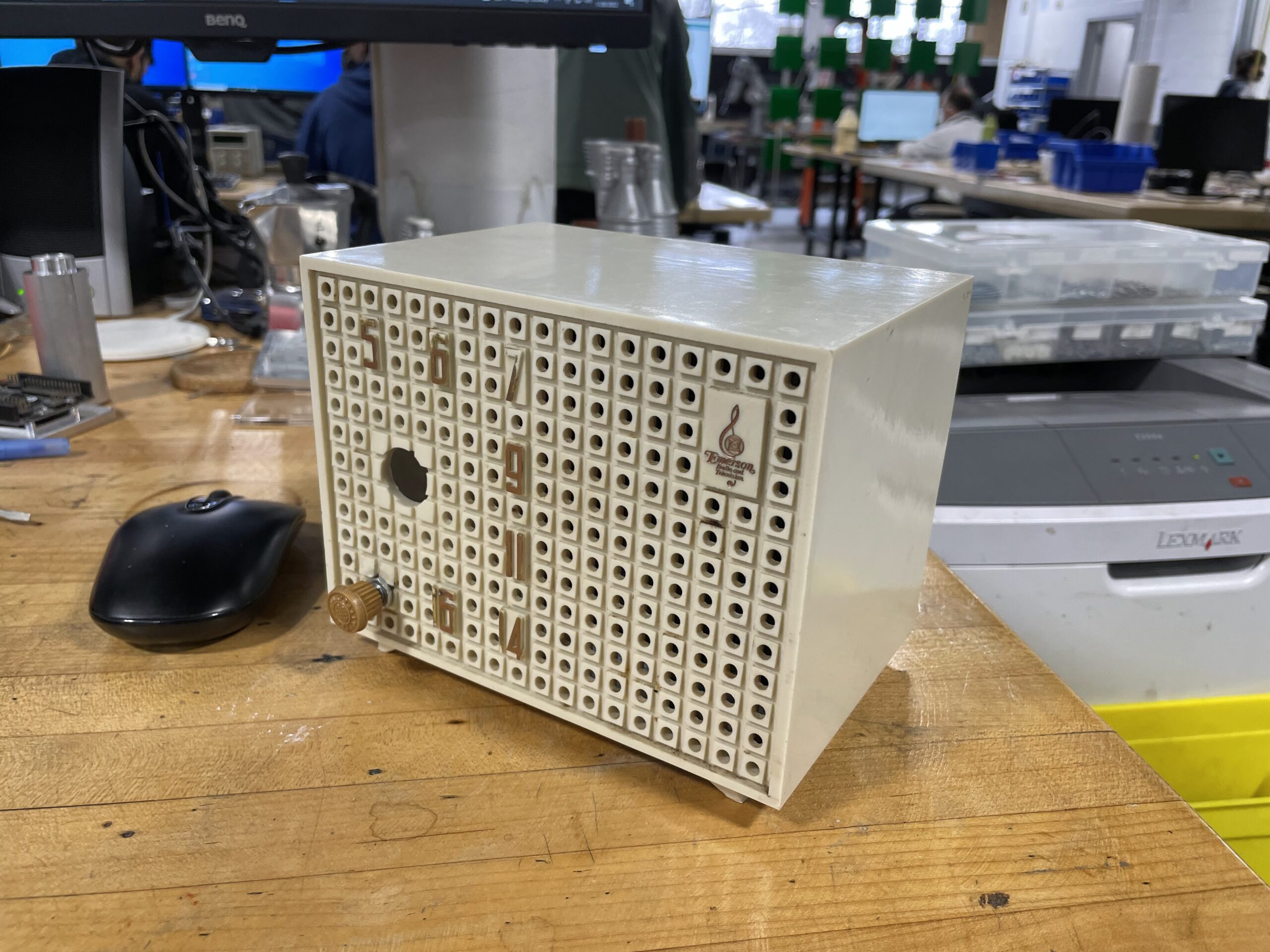
Worked on the Pi Radio today. Needed to do some soldering to create a 3.5 TS audio jack to a 2 pin connector for an amplifier. I used a Raspberry Pi as a 5v power source since it was just sitting at my desk. The audio jack is plugged into my computer speakers and is now playing sound through the speaker in the Emerson radio.
Next thing to do is make sure the code on the Raspberry Pi is working correctly and plug the audio jack into it. I will make final connections for the digital encoders and then take everything apart of repaint the casing. Getting very close. Here is a short video of some audio coming from the radio.
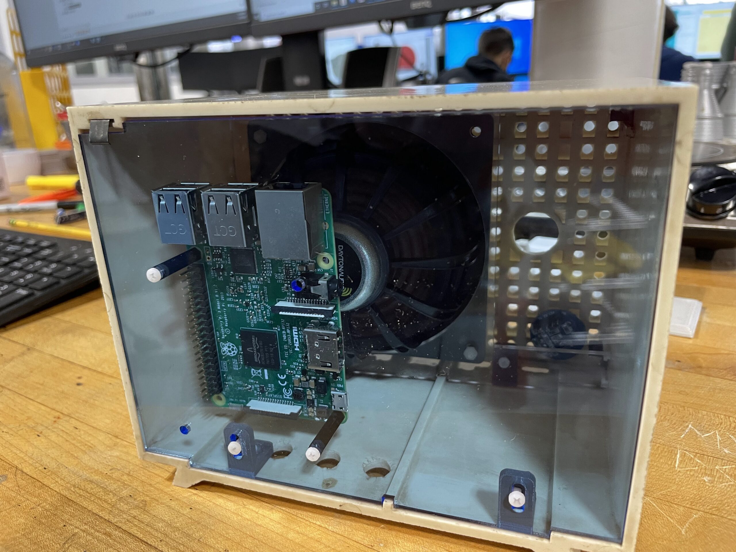
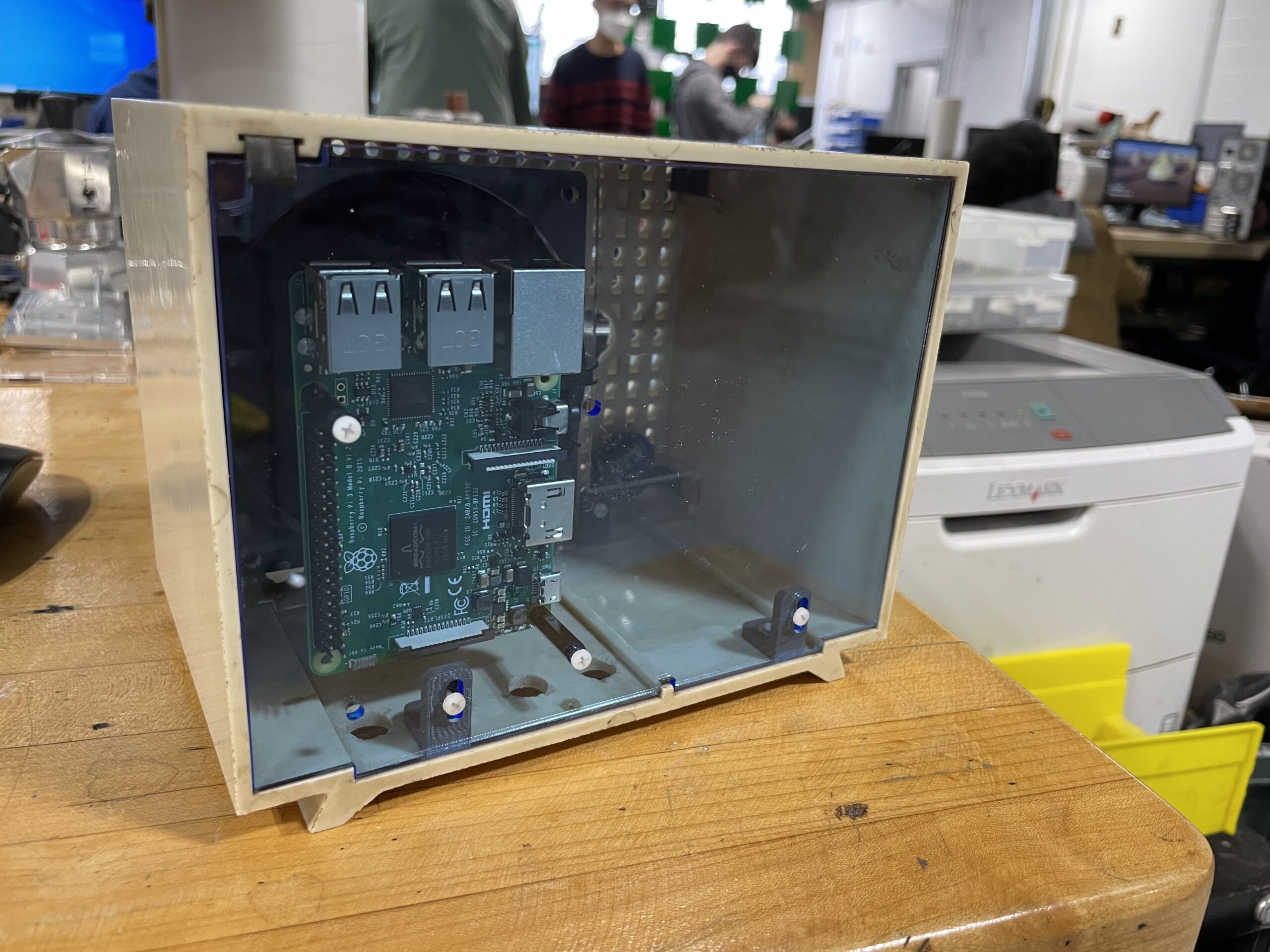
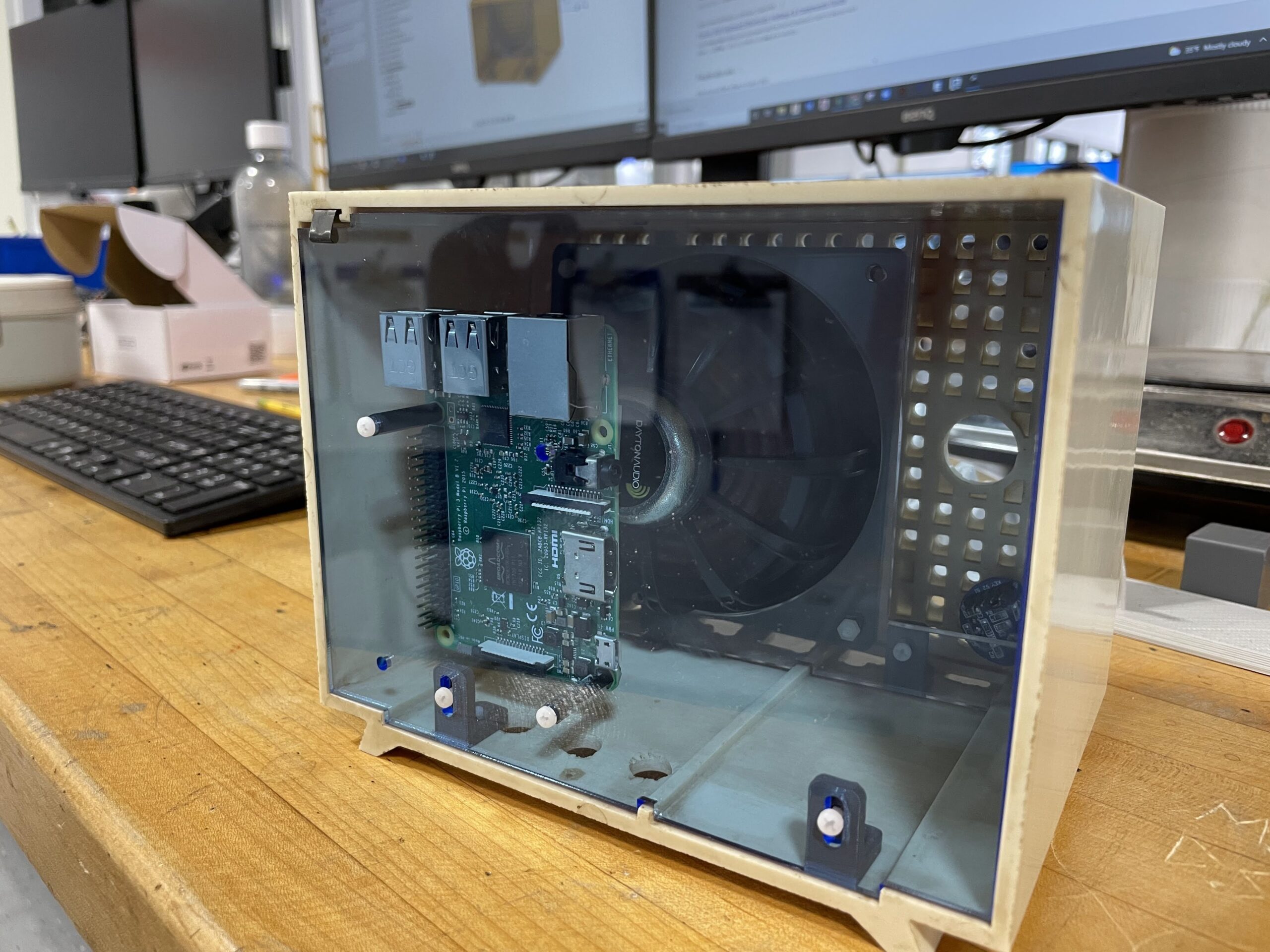
Just a quick update on the Pi Radio. I have been working on the internals and am close to having some nice acrylic mounting panels for the interior of the radio. Additionally, I have chosen a speaker to use, which will replace the old damaged speaker that was in the unit when it was purchased. The new speaker is a 4″ Dayton Audio DMA105 8 ohm, which is also being used by another student for a speaker project they are working on. Will post more on that project once it is further along. My radio needs a few more adjustments to the CAD model, and a couple of more test fits before we can wire it up and test my co-teacher’s coding with the Raspberry Pi. A few photos below showing the updated components inside the radio housing.
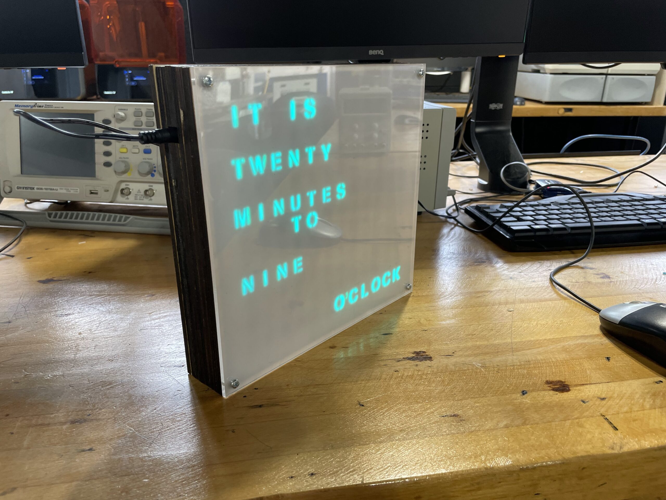
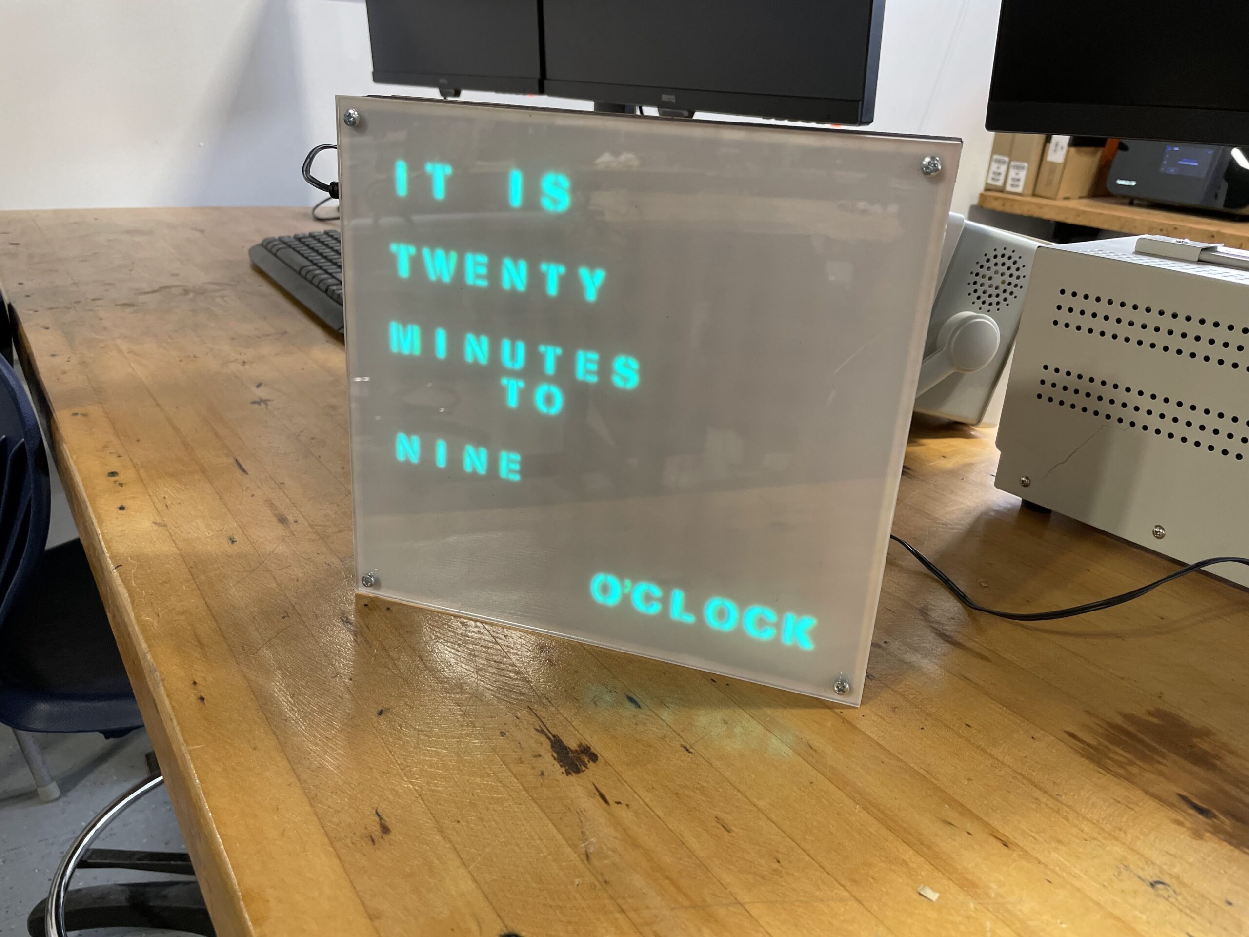
It’s taken quite a while, but the LED Word Clock looks to be finished. This was a project started a few years ago by some students, and then was completely redone by a current Junior from our shop. This student has spent most of the semester putting the project together in a manner that looks professional, like a product off the shelf.
The design uses about 10 layers of lasercut wood to conceal the wiring and house the lettering and spacing pieces. The circuit board is custom made on our Bantam Tools PCB mill, and all the wood and acrylic were cut on our Epilog Fusion Pro. Just a few photos below of the finished product, hoping to have a more detailed writeup of the process from the student.
One of my favorite aspects of my job is solving a problem we have never before encountered. Luckily, this happens nearly every day as students are building various types of projects of their own design, such as candy shooters and singing toothbrushes.
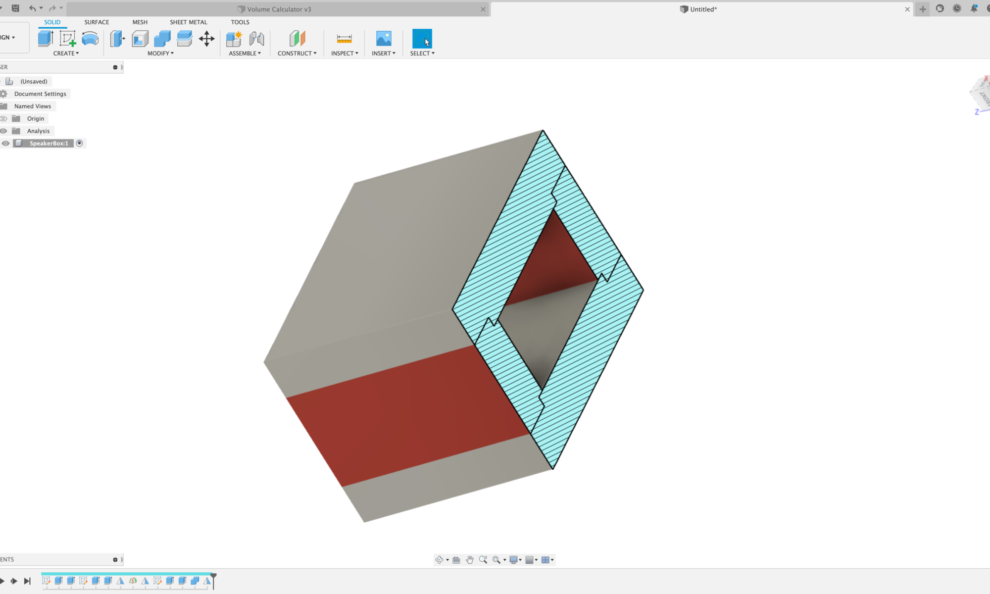
A senior was having problems building a box for a bluetooth speaker setup they were working on, as they were trying to understand how to build the box with the proper volume specified for the speakers he was using. He was taking measurements, putting them into CAD, but when things changed within his project, he would have to change all his dimensions again and it was a real tedious task.
Working together we were able to solve the problem using parameters in Fusion 360. We utilize Fusion 360 for all our CAD needs in the classroom. It’s an easy to learn, robust software with built-in CAM that enables us to send our models to all the different machines we have in the shop – 3D printers, waterjet, plasma cutter, mills, lathes, etc. It’s also free software, and I have the ability to setup an educational account and give access to all my students, rather than having each student setup their own personal account. I really like the way they have the new educational account setup for teachers and students, makes life much easier than before where students needed to verify their accounts which was often problematic.
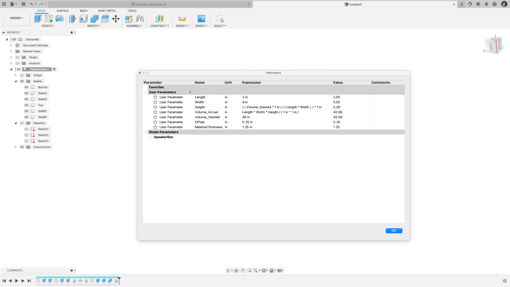
Back to the parameters discussion. By utilizing parameters in Fusion 360 along with an organized modeling strategy, we found a way to control the volume of the box so it always remains constant, even when we change the length, width, or size of material. Below is a screenshot of the parameter setup for the project. You’ll notice some odd math happening, as there are several instances of multiplying 1 in within an expression. This is because Fusion 360 does not have in² or in³ within its parameters framework, so you need to use the 1 in to cancel out parts of an expression so it has the same units Fusion 360 can work with.
I went ahead and created a quick modeling video for students, so in the future I can just point them to the video instead of showing them directly, which frees me up to help other students in our classroom. Video below.