LED Acrylic Light Box

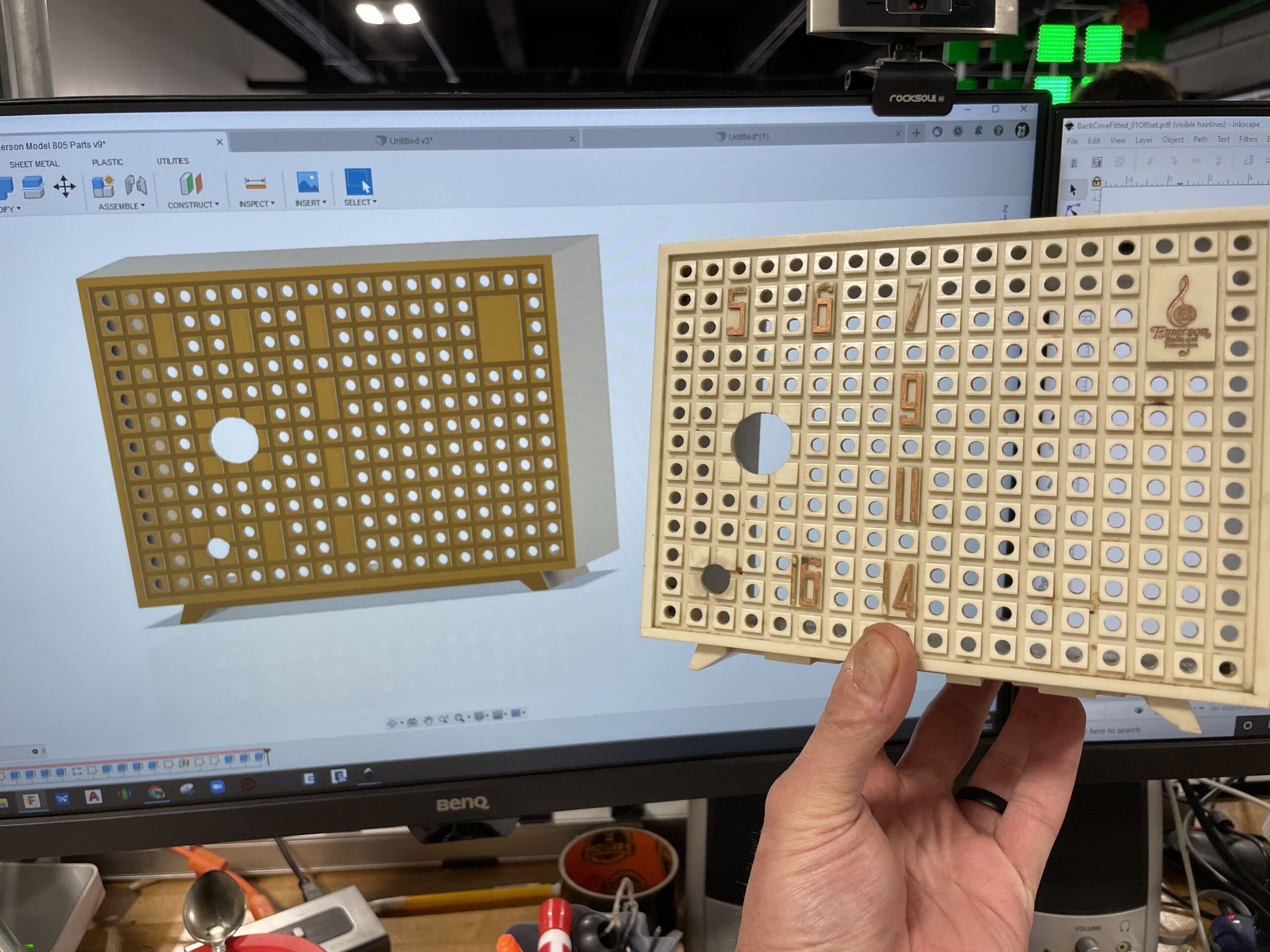
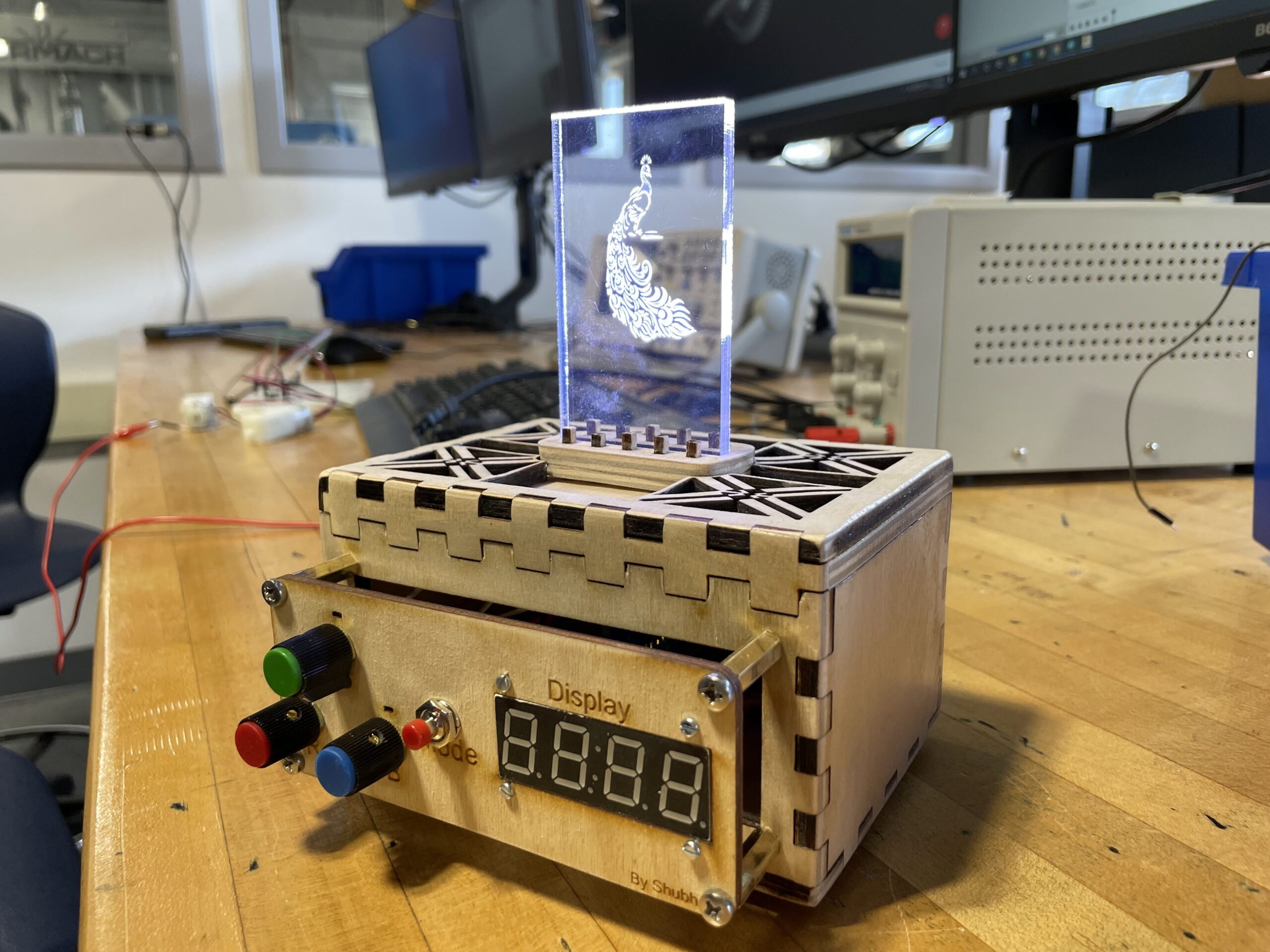
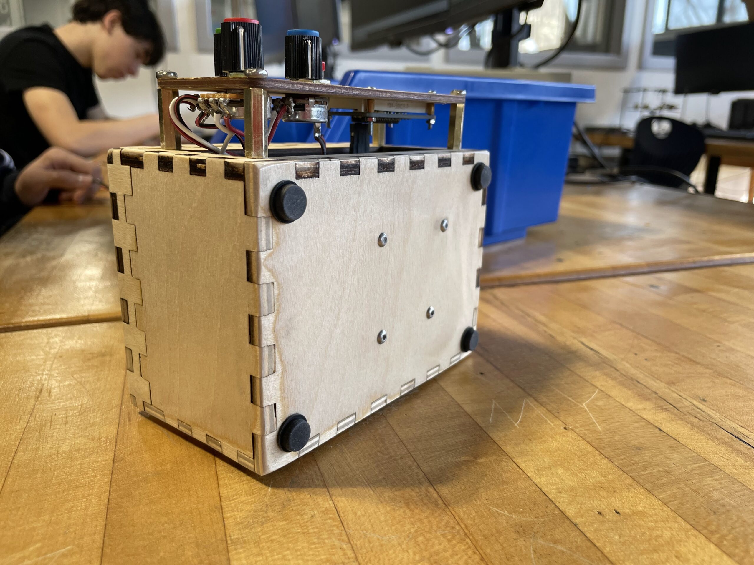
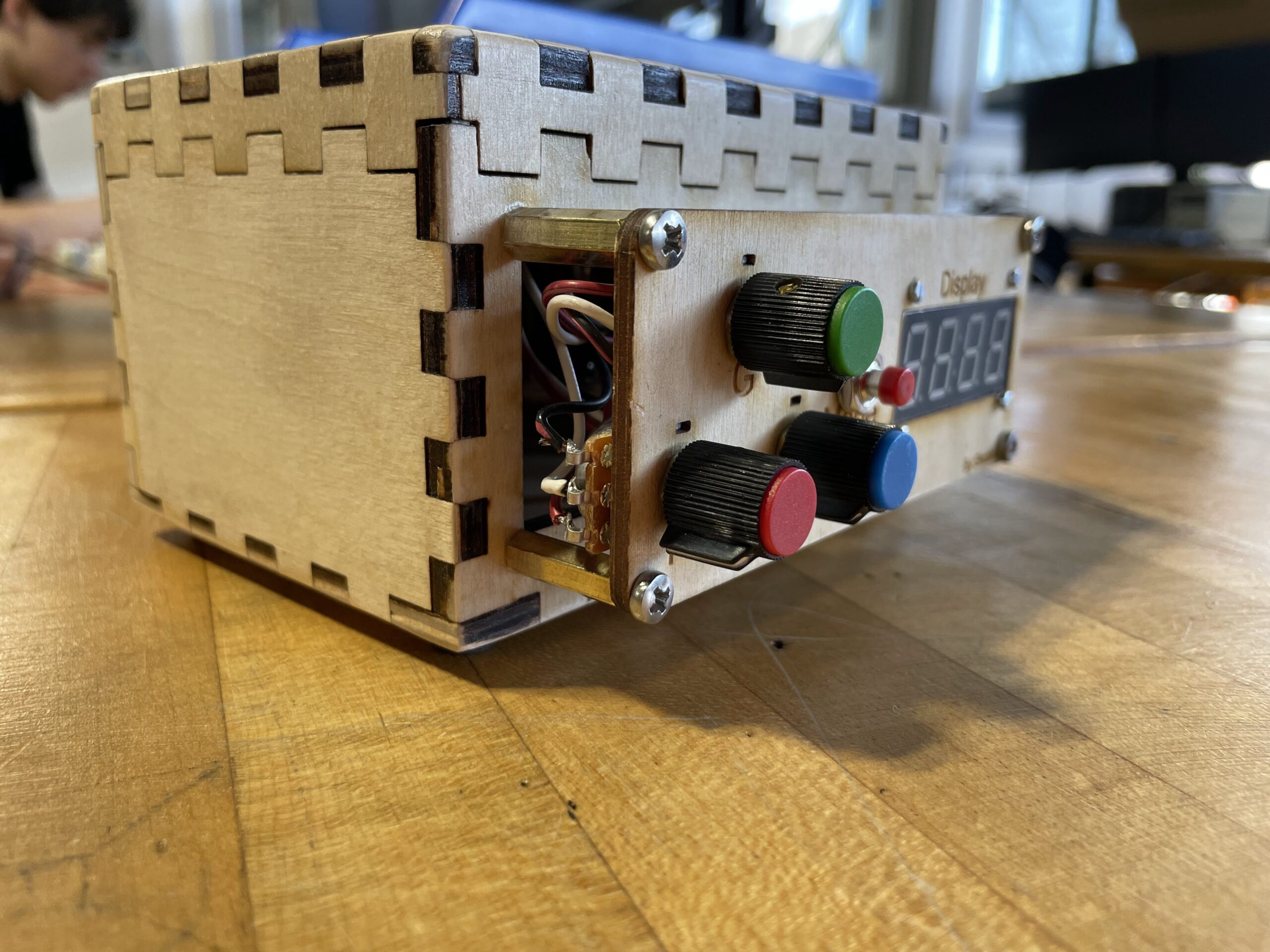
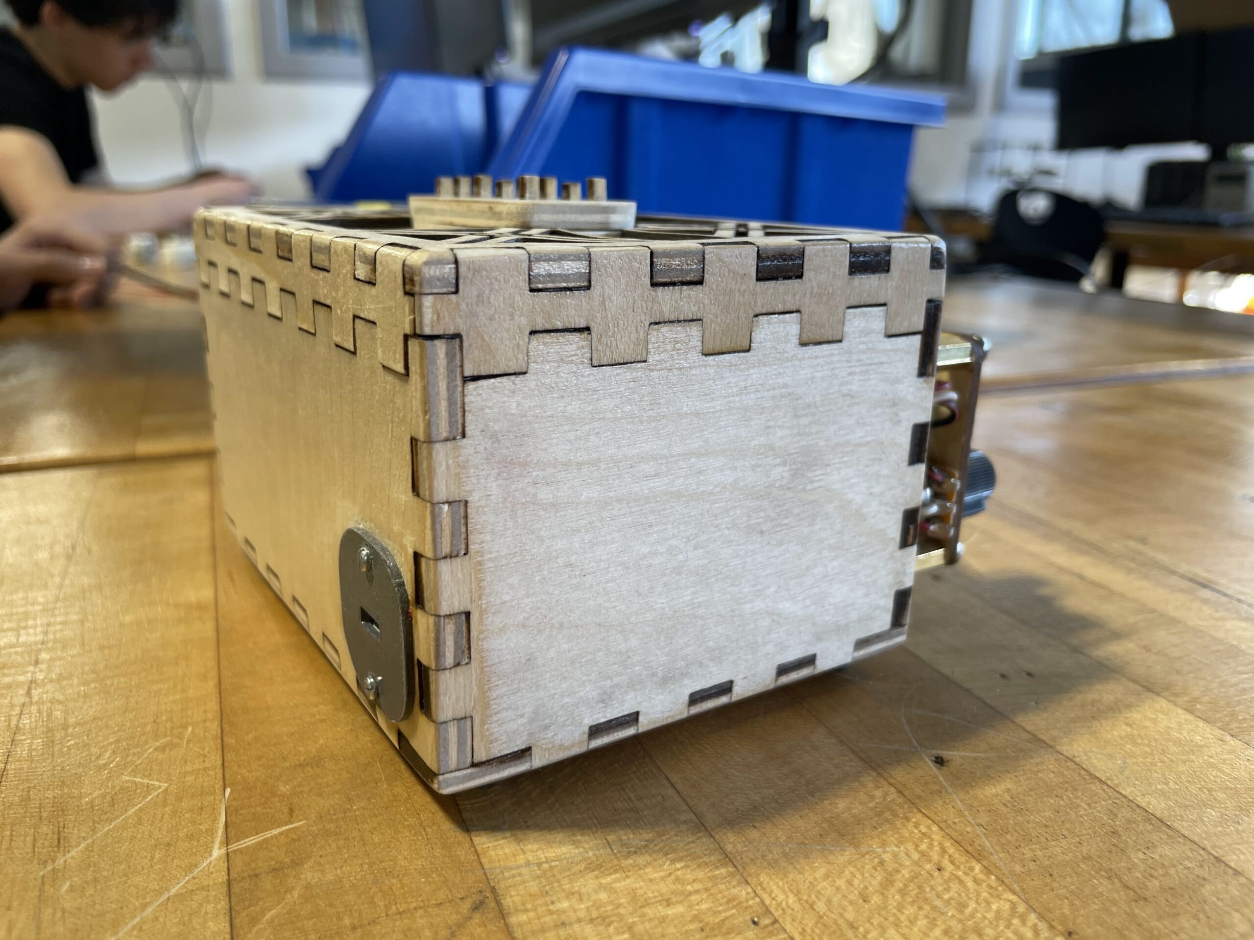
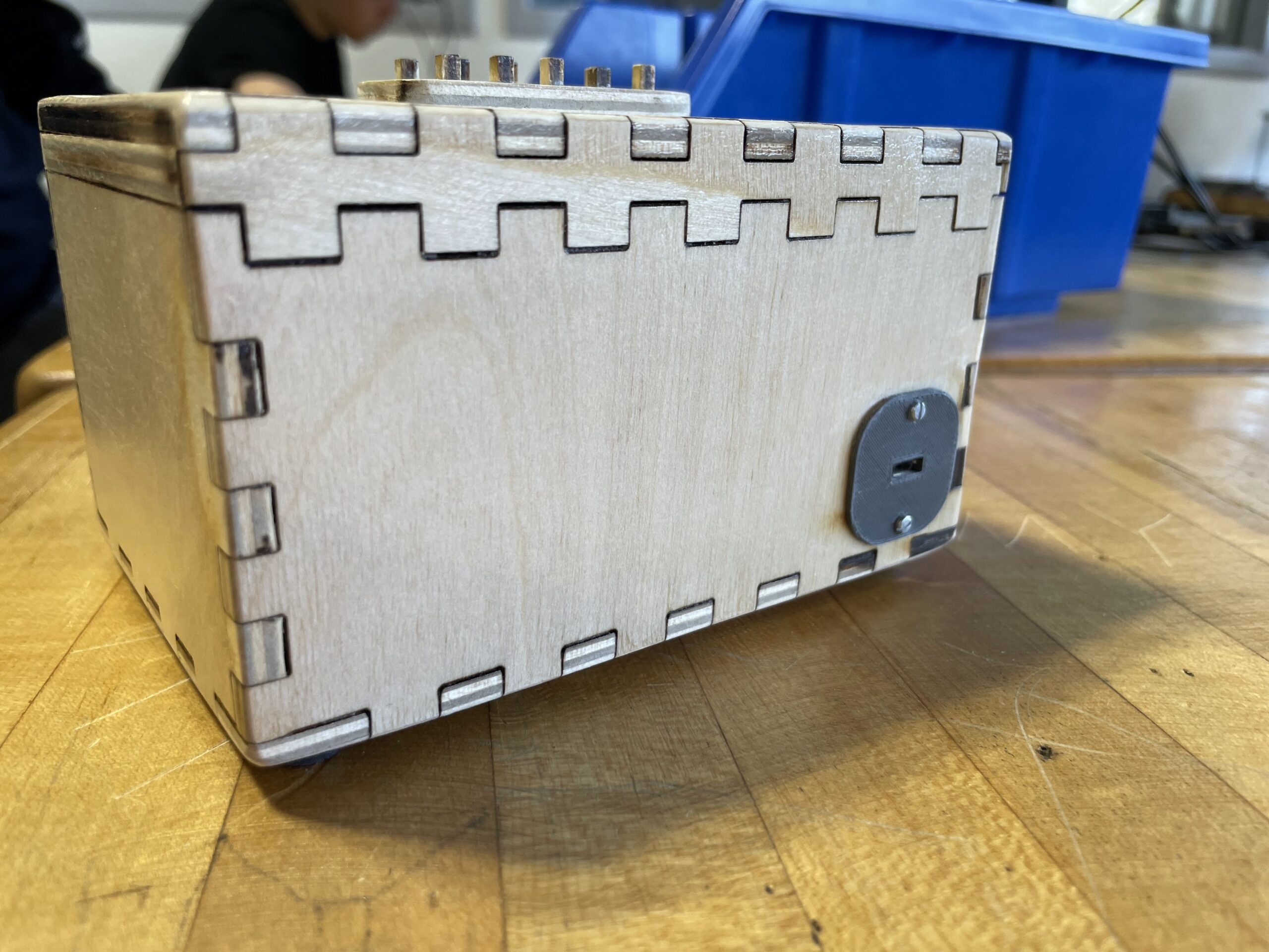
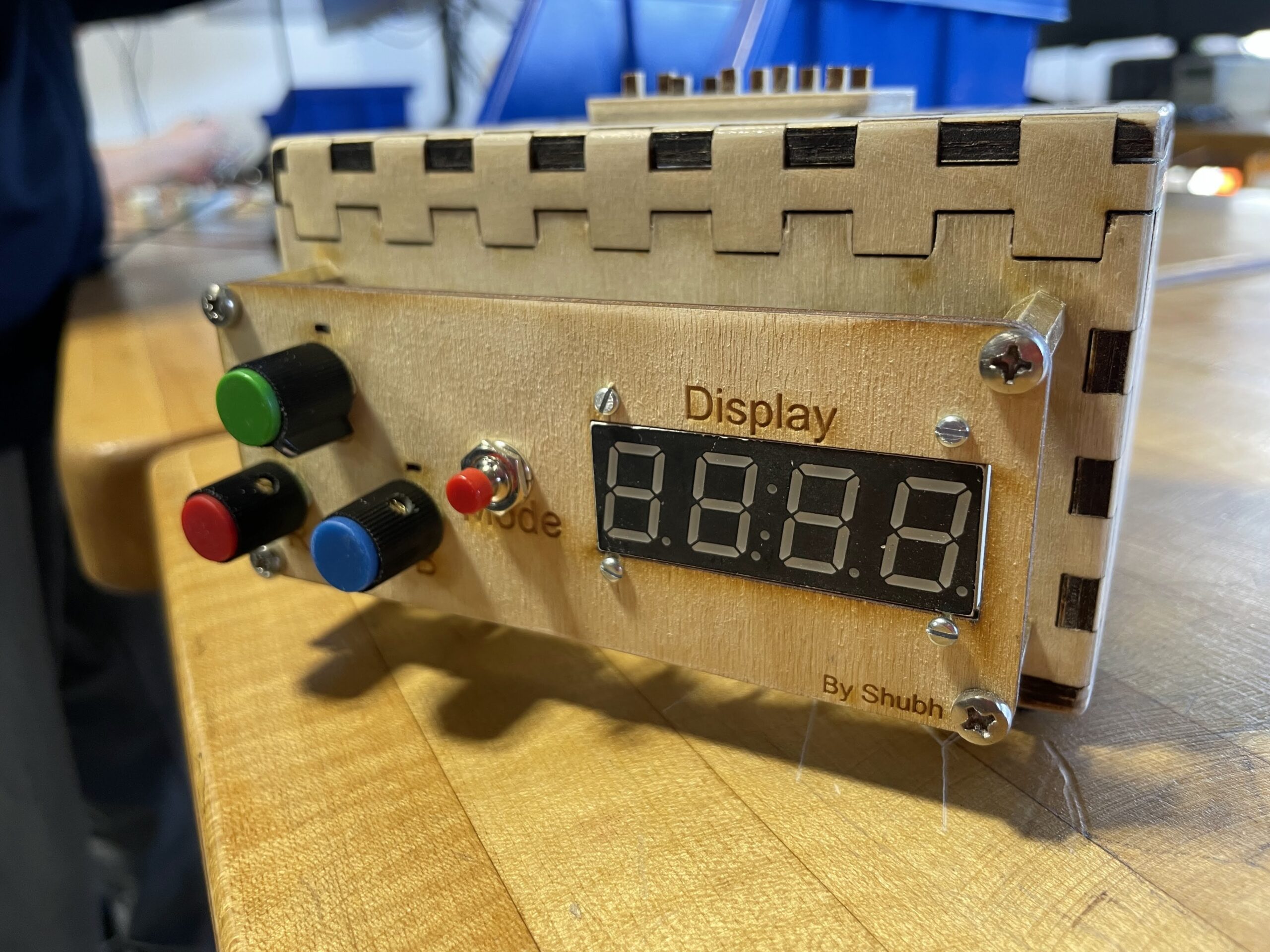
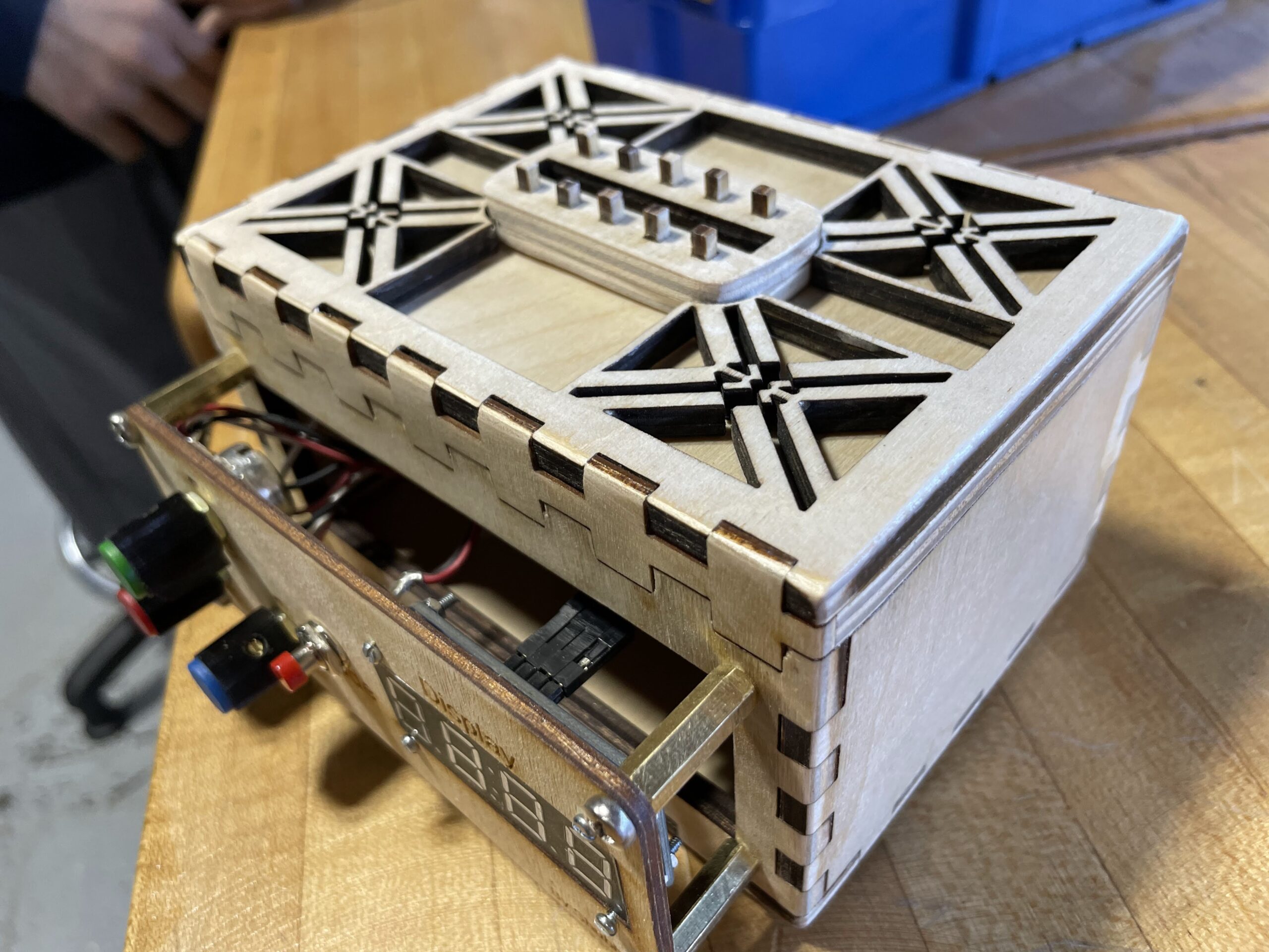
Wanted to showcase a few projects that are happening in the shop right now. The first is from one of our sophomores, Shubh P ’24, who took the design on on his LED Light Box to another level. Shubh has put a lot of attention to detail in his project from CAD to circuitry. He introduced several types of circuitry components to the design, which include potentiometers as dials, 7 segment display, and pushbutton switches. In addition, he utilized different sized wood in his CAD model to create patterns within the framework of the structure of the box. It really turned out well. Unfortunately, when taking photos of it today, there was a minor glitch in the coding, so he is going to fix the issue and I will post some more photos below.

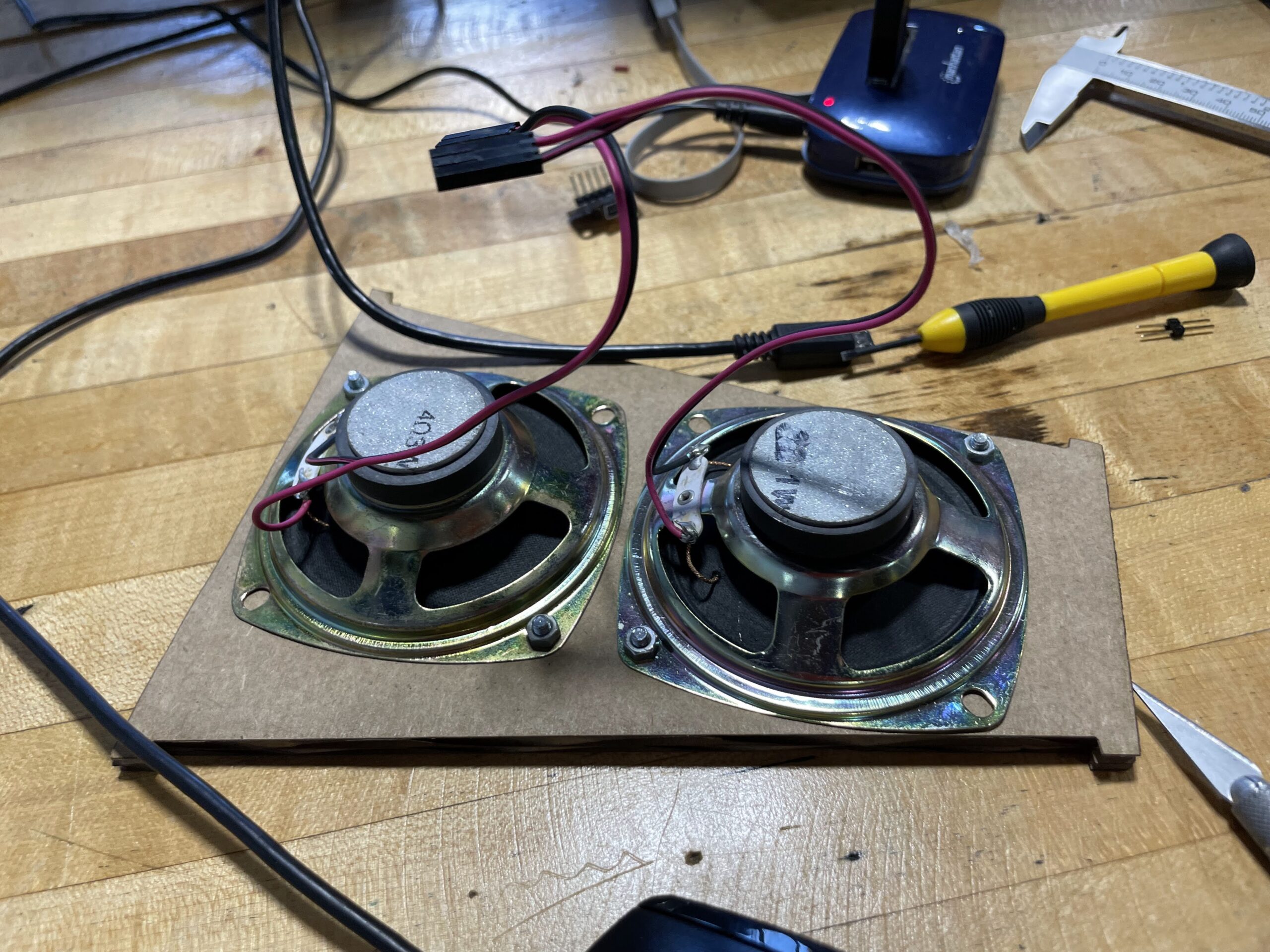
In addition to the light box, Prince A ’23 is working on updating an older project from a previous student, a bluetooth speaker. The circuitry for the project is being modernized, as is the speaker box. Below you can see some test fitting of speakers in cardboard.

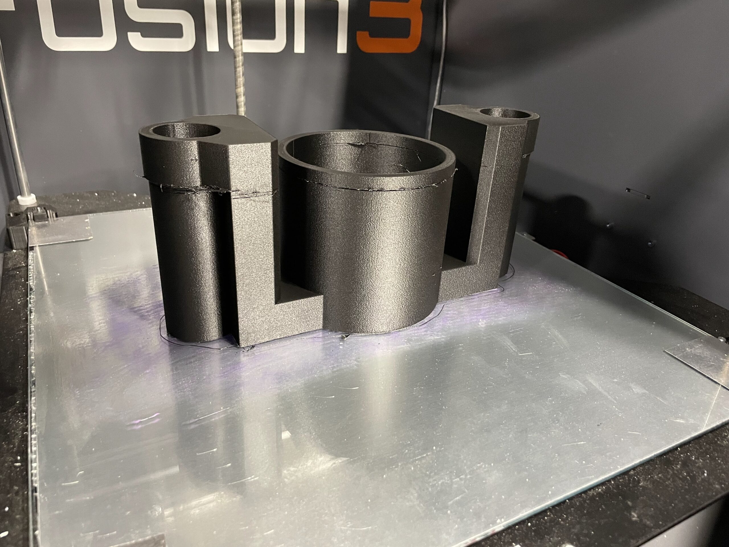
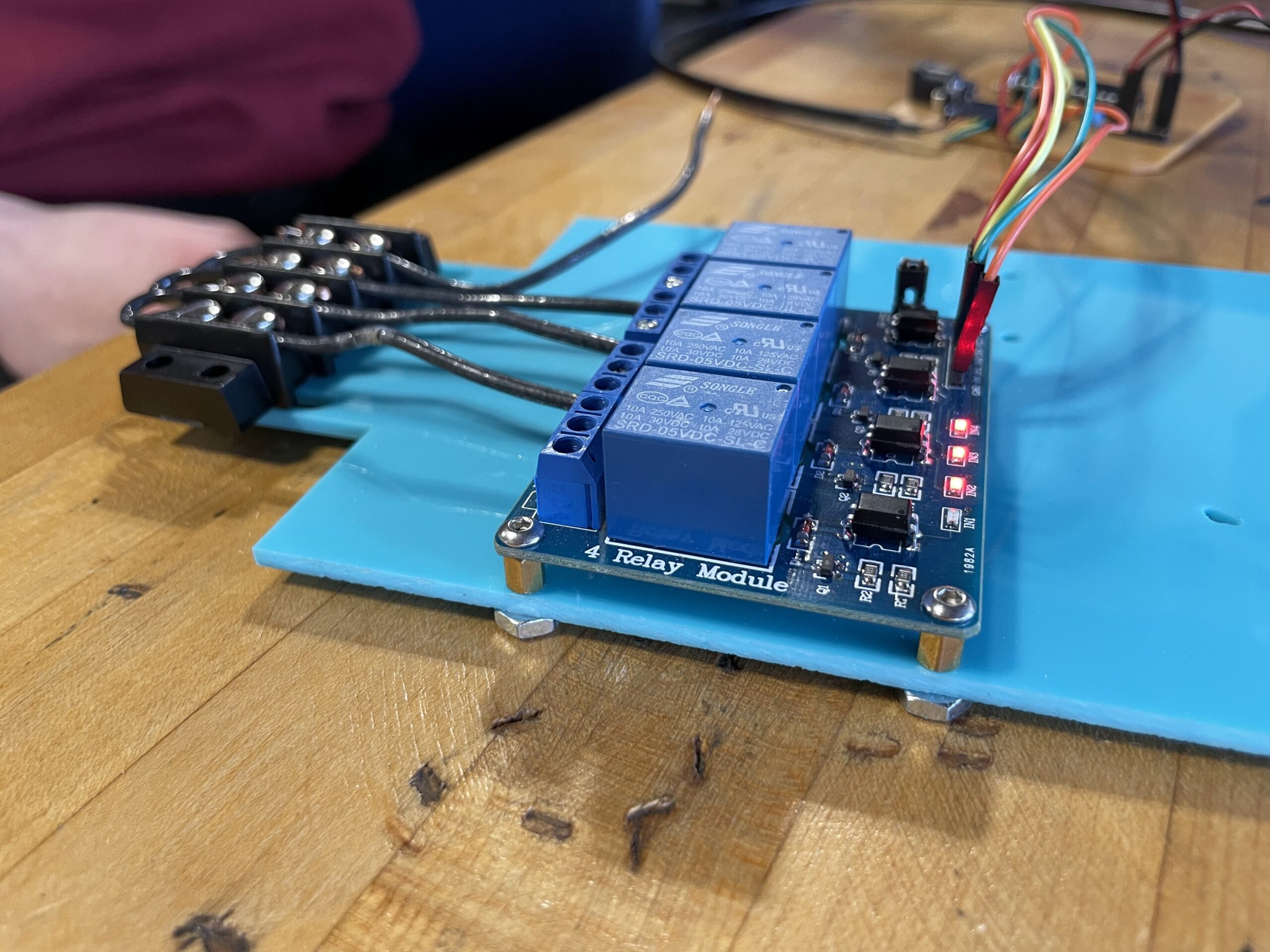
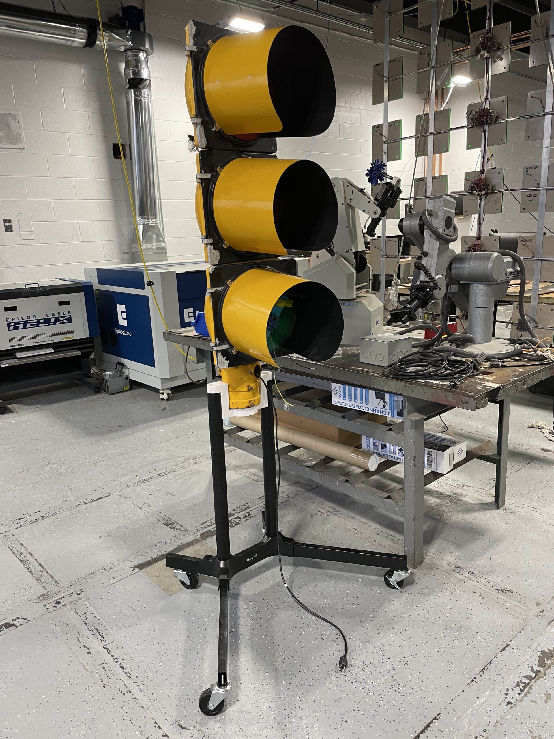
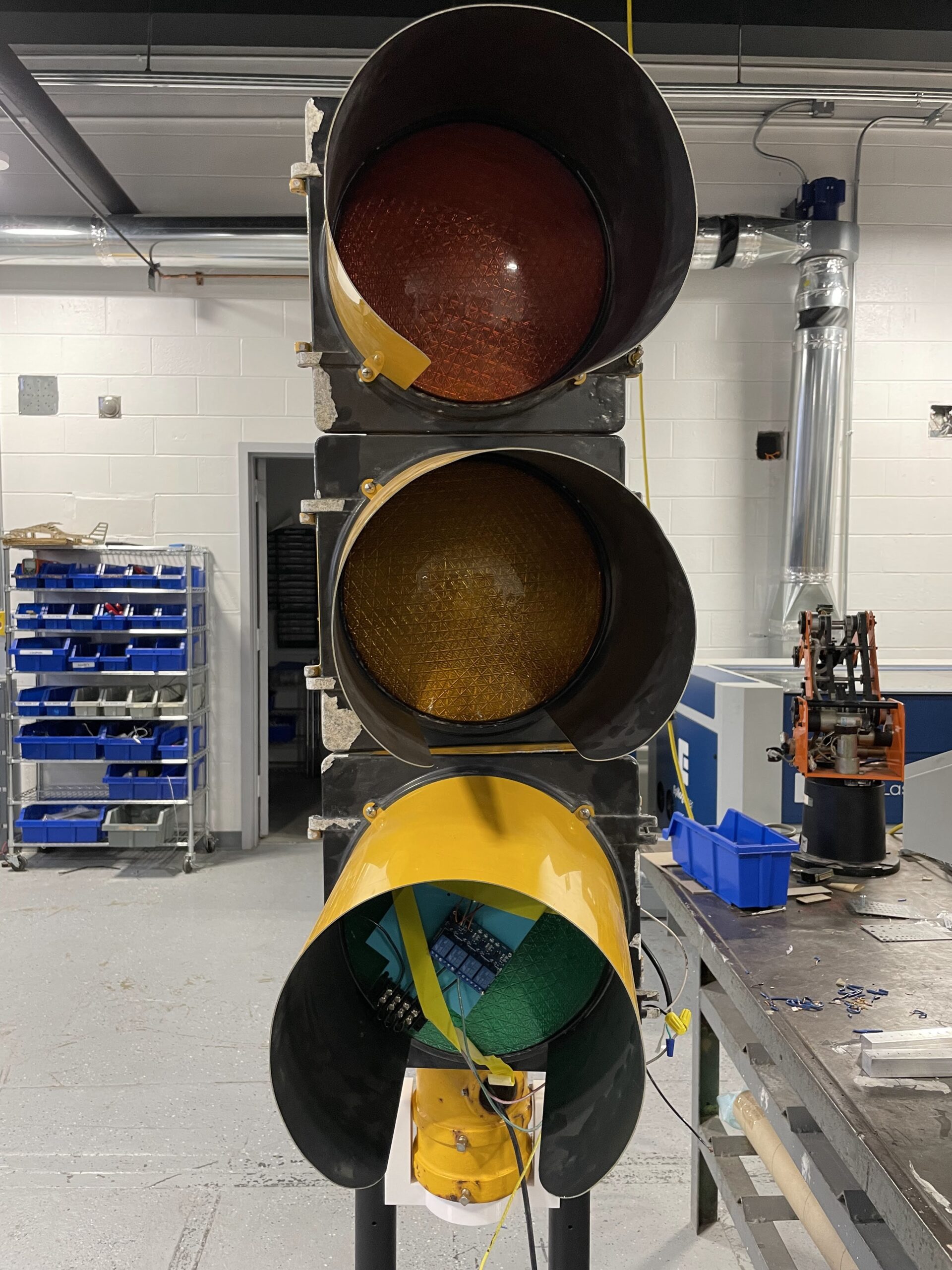
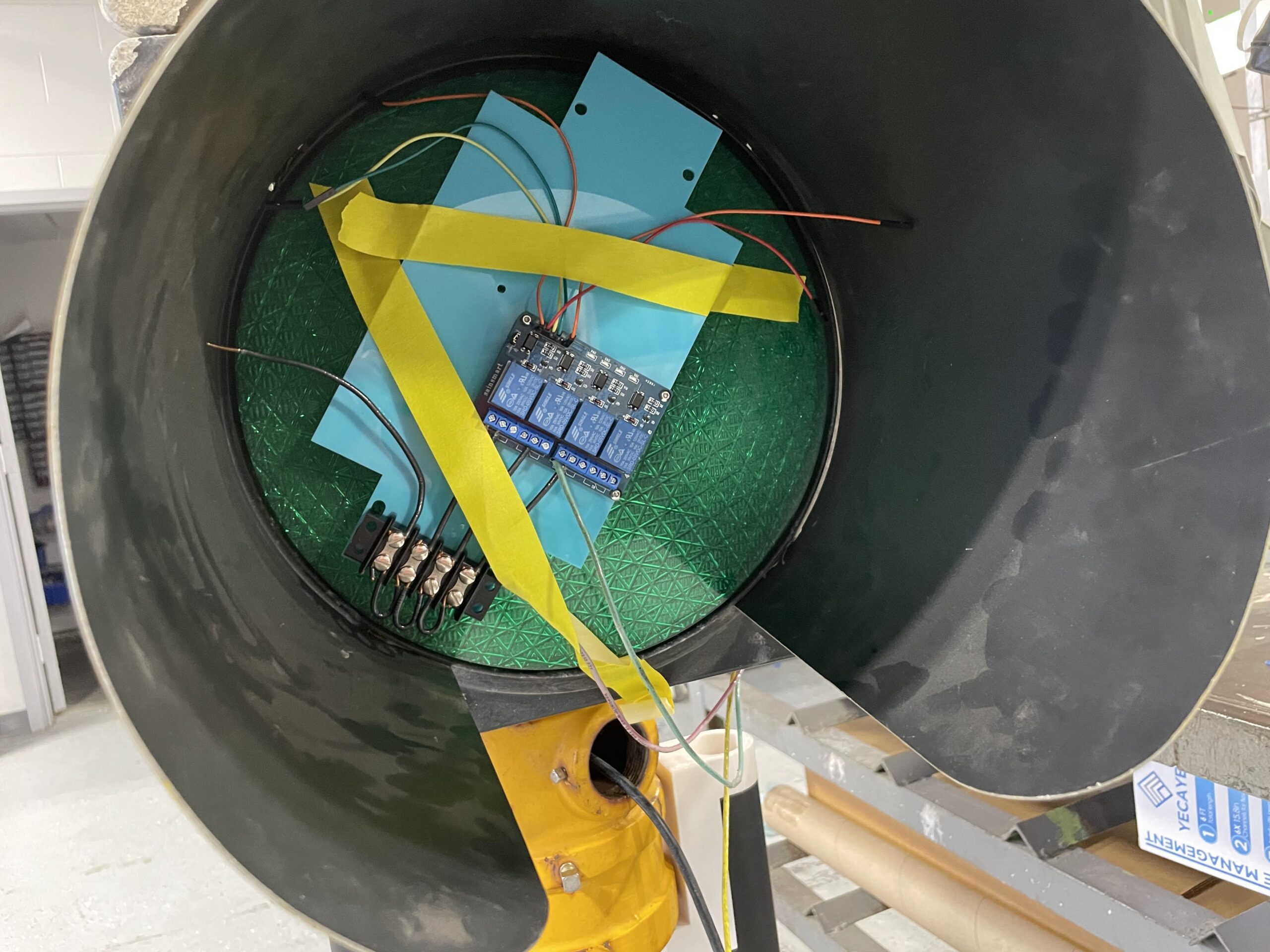
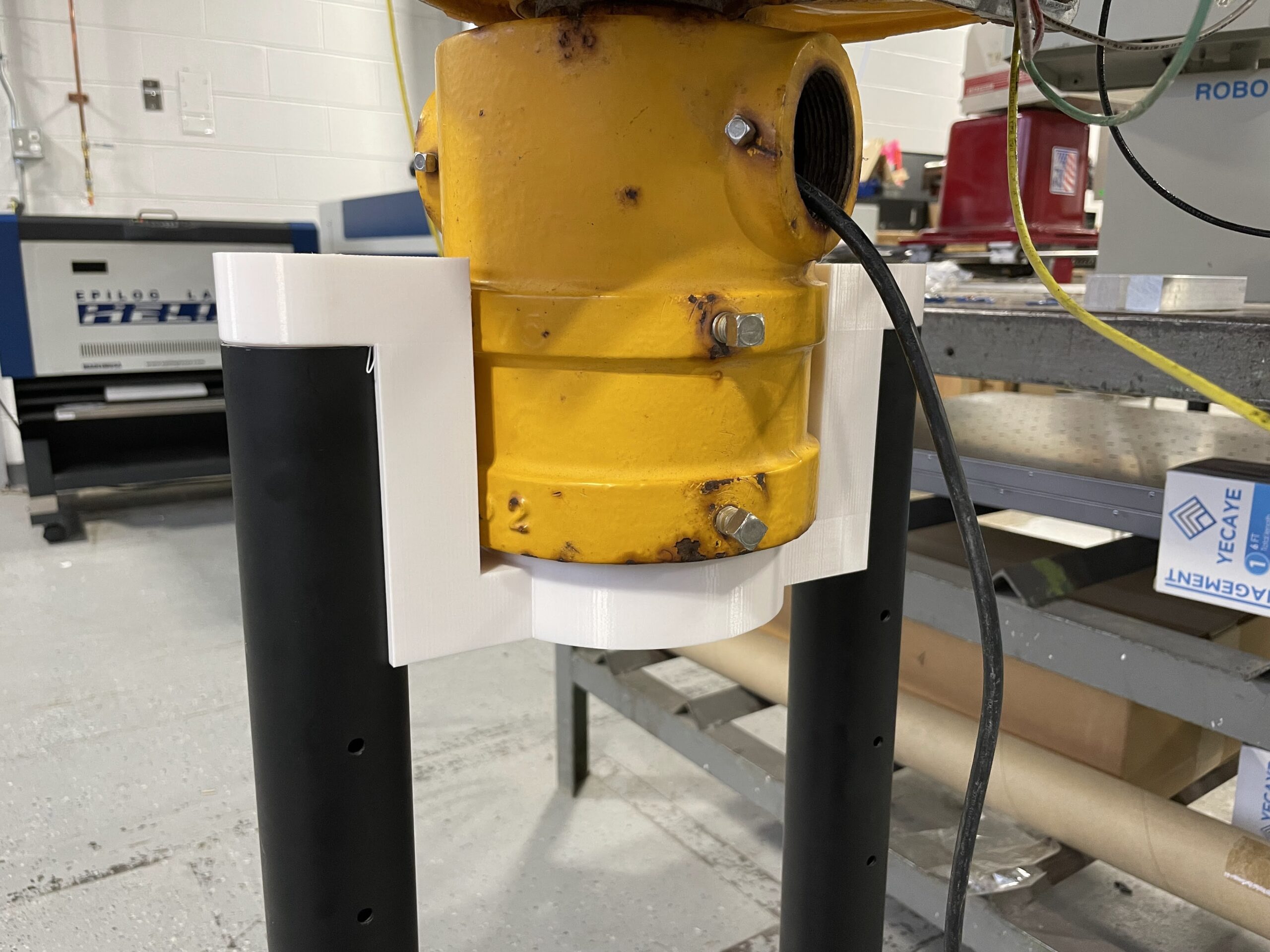
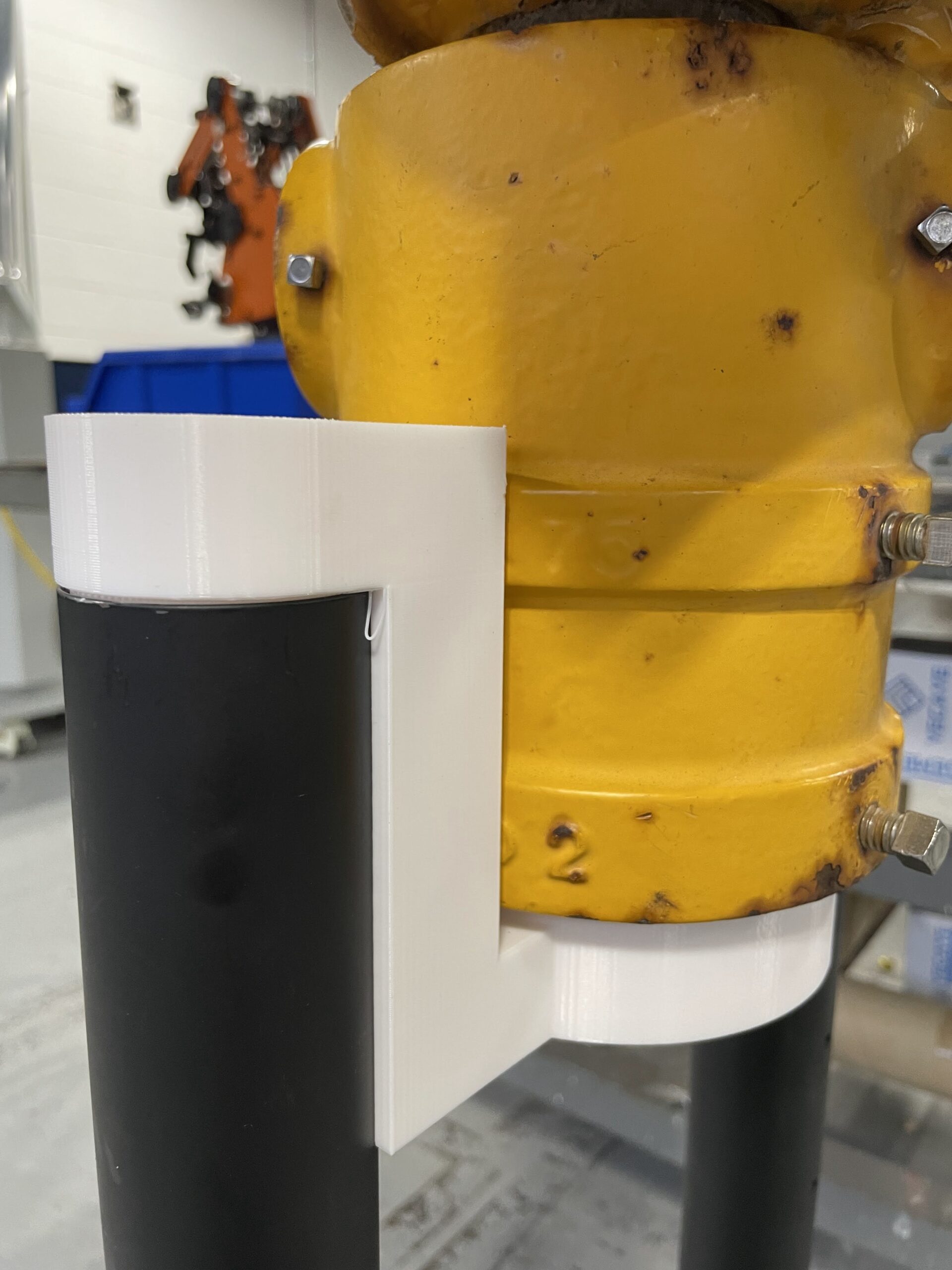
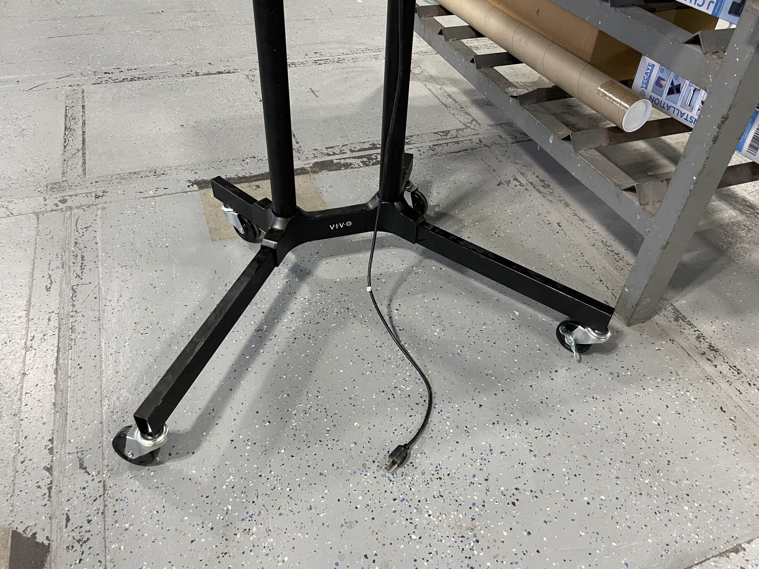
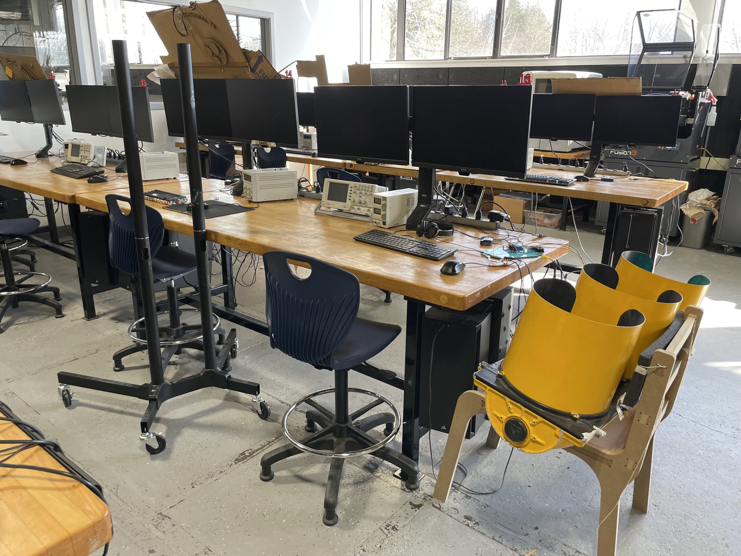
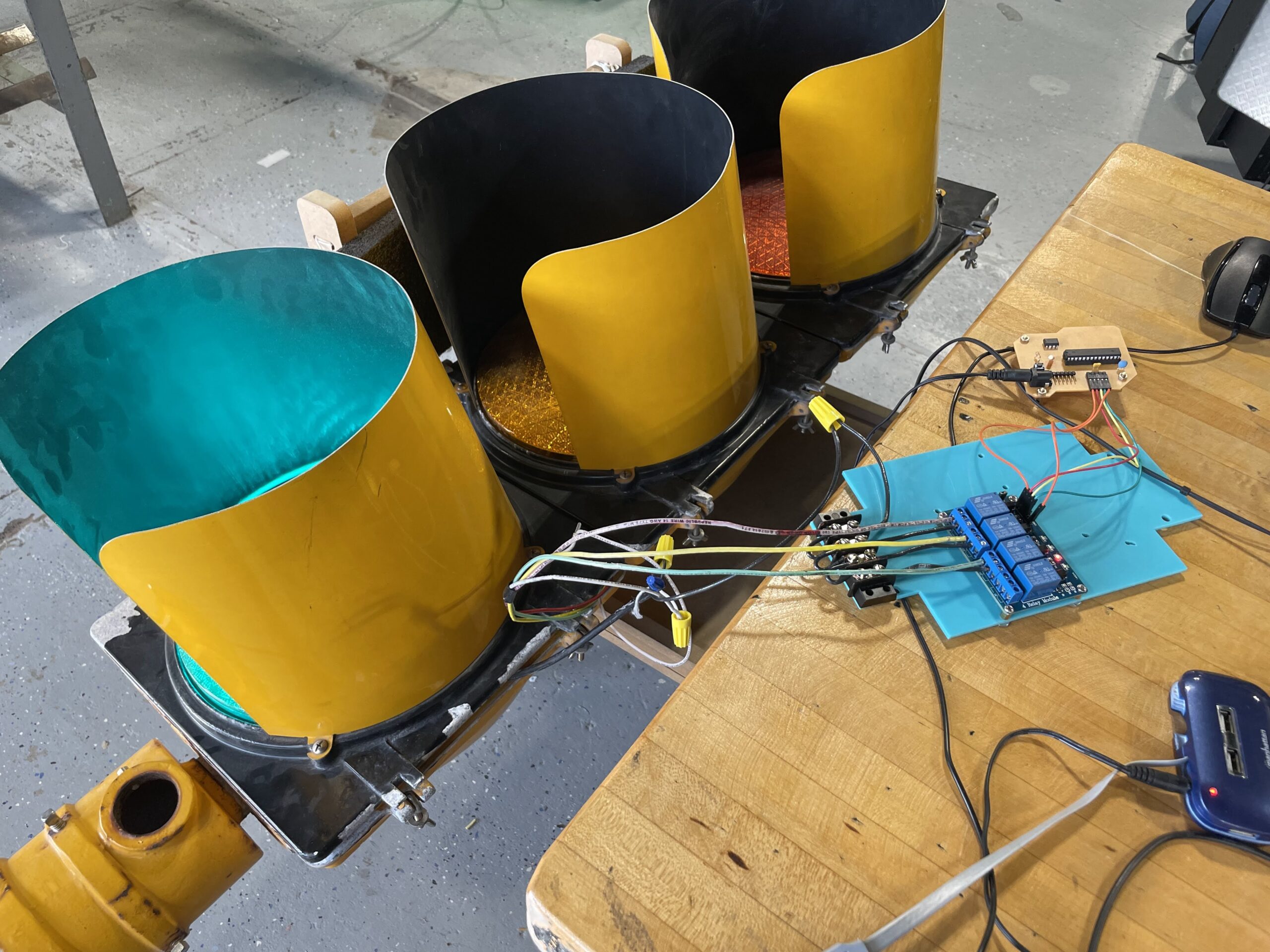
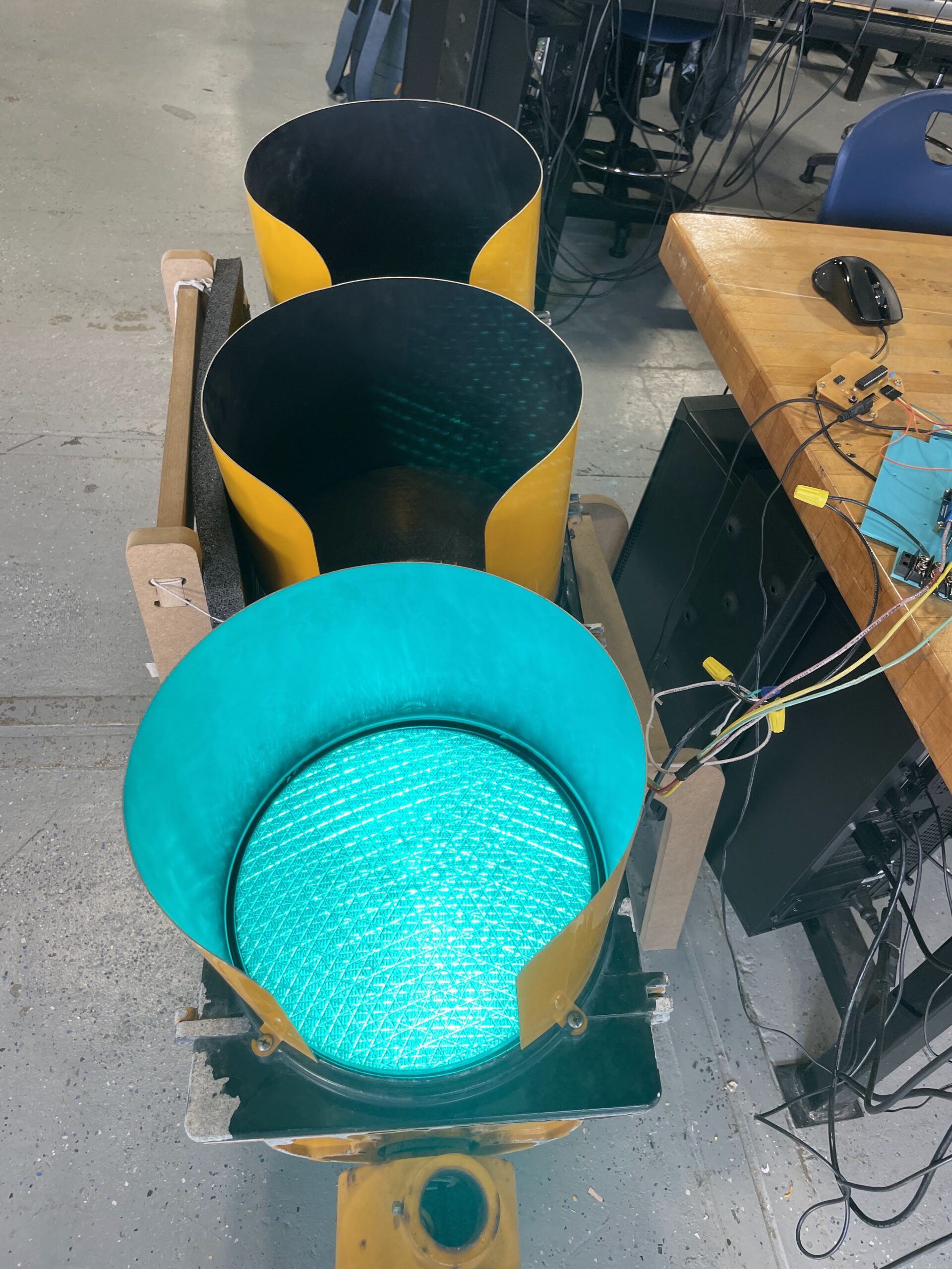
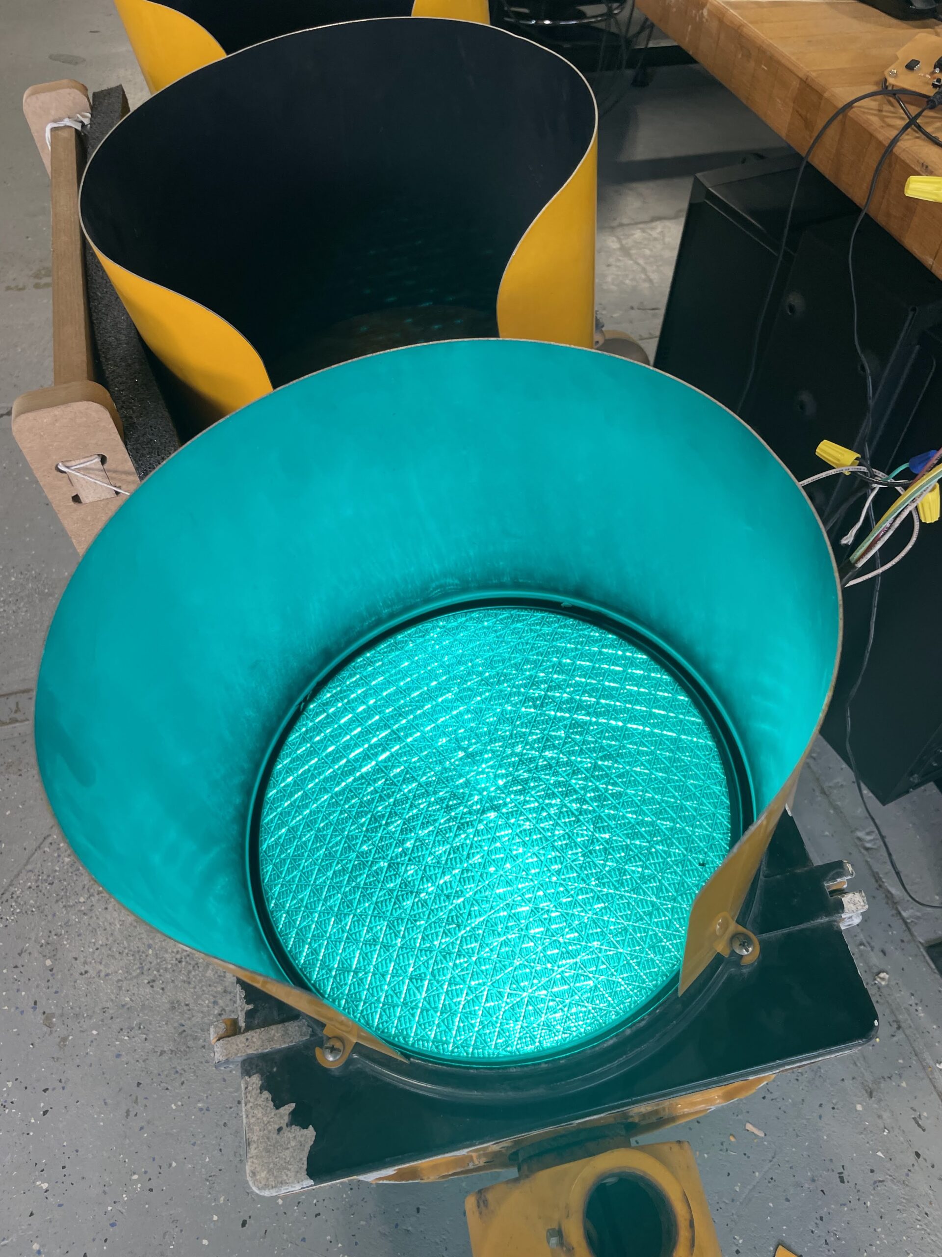
And lastly, Clark B ’23 and Daniel R ’22 are working on getting our traffic light fully functioning. Clark has been making circuit boards on our Bantam Tools mill and writing code to make the light work in unison with the school’s bell system. You can see his array of relays below in blue. Daniel has designed a connector to fit the traffic light on an old tv stand. We decided to print the connector out of a carbon fiber filament for strength, and after some trial and error, we are pretty happy with the final result. You can see it below in black.

Red Light, Green Light

Junior student Clark B has been working on circuitry to control an actual Stop Light that was donated to the shop a few years ago. Many students had thought about working on a project with the Stop Light, but nobody truly took on the project as Clark has done. So far he has written a program for an Arduino that will allow the light to turn on to reflect the daily class schedule. Green light for when we are in class time, yellow for 5 minutes before the bell, and red for time between classes. Along with his Arduino, he has a relay to control the AC voltage that turns on the light.

Additionally, we repurposed an old rolling television stand that was being dumped in the trash. The wheels were broken so we drilled new holes in the steel frame, tapped the holes for M10 bolts, and used some new casters we had in our storage room. To connect the light to the stand, another student, Senior Daniel R, 3D modeled and printed a connecting element that rests on the poles of the TV stand, and allows the Stop Light to slip onto the top of the connector. It’s coming together very well at the moment, and just a little more wiring and finalizing the coding should complete the project. Will post again when completed. For now, some photos below.

Stop Light

The Stop Light project continues with Junior Clark B. ’23 working fastidiously each day. Clark had the code working on a breadboard, and has spent time using Eagle to create a custom PCB on our Bantam Tools PCB mill. The process of learning how to create a pcb in a CAD/CAM software such as Eagle is very difficult, so kudos to Clark for working through it. As we have found, however, the first attempt at creating a board is usually not the final board – as it tends to take a few efforts before the final working prototype is complete.

When the pcb was coupled together with the relay for high voltage and the light, everything turns on, just now exactly when we want it to. There is probably an error in the code, so Clark needs to spend some time debugging. Still, it’s very close to working properly, ie. following our school schedule, and we have found a stand for it, having repurposed a rolling TV stand that was being thrown away by the Media Tech shop. Hopefully we will be able to present the final version soon. A few in process photos below.

Pi Radio Internals

Just a quick update on the Pi Radio. I have been working on the internals and am close to having some nice acrylic mounting panels for the interior of the radio. Additionally, I have chosen a speaker to use, which will replace the old damaged speaker that was in the unit when it was purchased. The new speaker is a 4″ Dayton Audio DMA105 8 ohm, which is also being used by another student for a speaker project they are working on. Will post more on that project once it is further along. My radio needs a few more adjustments to the CAD model, and a couple of more test fits before we can wire it up and test my co-teacher’s coding with the Raspberry Pi. A few photos below showing the updated components inside the radio housing.

Pi Radio – It’s Alive

I had mentioned the Pi Radio project to my co-teacher and he was pretty enthusiastic about working on it. Since he is the coding expert, I decided to let him work out those specifics, while I work on the CAD aspects and building the project once the electronic portion is complete. Today he successfully coded the Raspberry Pi to tune to different internet radio stations using a rotary encoder, which will mimic using the tuner from the radio to ‘tune’ to different stations. Additionally, he has incorporated a second rotary encoder for volume control. Everything seems to be working now, but still some work finalizing the code and electronics.

For my part, I’ve started putting the entire radio into CAD in order to make all the new interior components to hold the new electronics. I’ve finally finished recreating the outer housing, and took a quick photo to show how well it came out. Looks just like the real thing. Next, I need to create some new components for lasercutting and 3D printing.