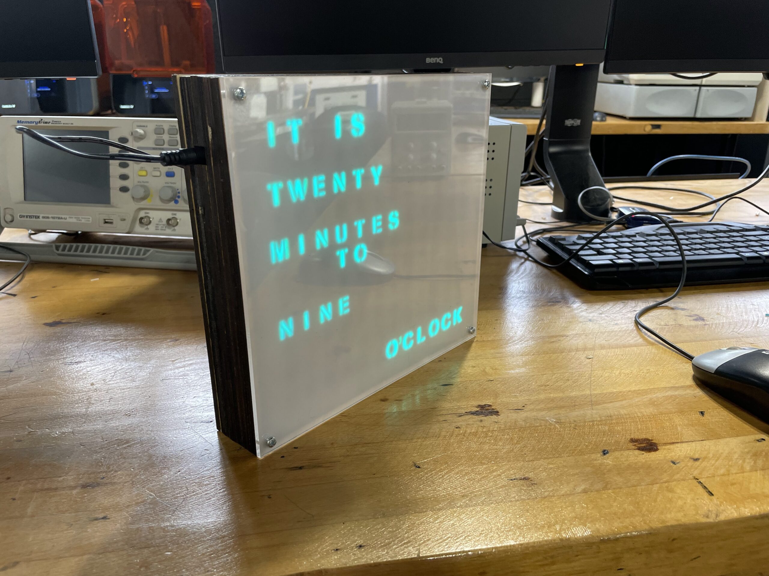
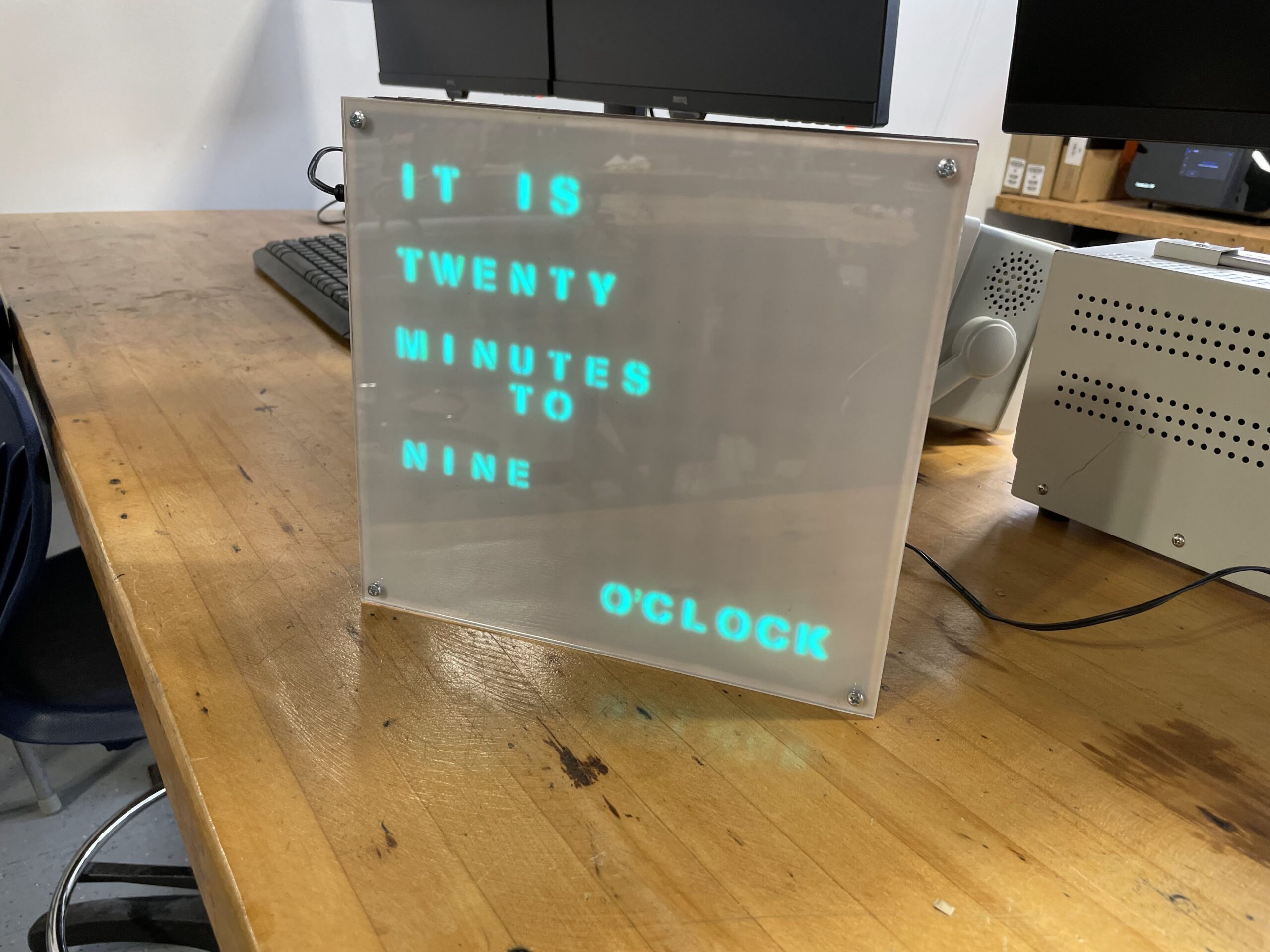
It’s taken quite a while, but the LED Word Clock looks to be finished. This was a project started a few years ago by some students, and then was completely redone by a current Junior from our shop. This student has spent most of the semester putting the project together in a manner that looks professional, like a product off the shelf.
The design uses about 10 layers of lasercut wood to conceal the wiring and house the lettering and spacing pieces. The circuit board is custom made on our Bantam Tools PCB mill, and all the wood and acrylic were cut on our Epilog Fusion Pro. Just a few photos below of the finished product, hoping to have a more detailed writeup of the process from the student.
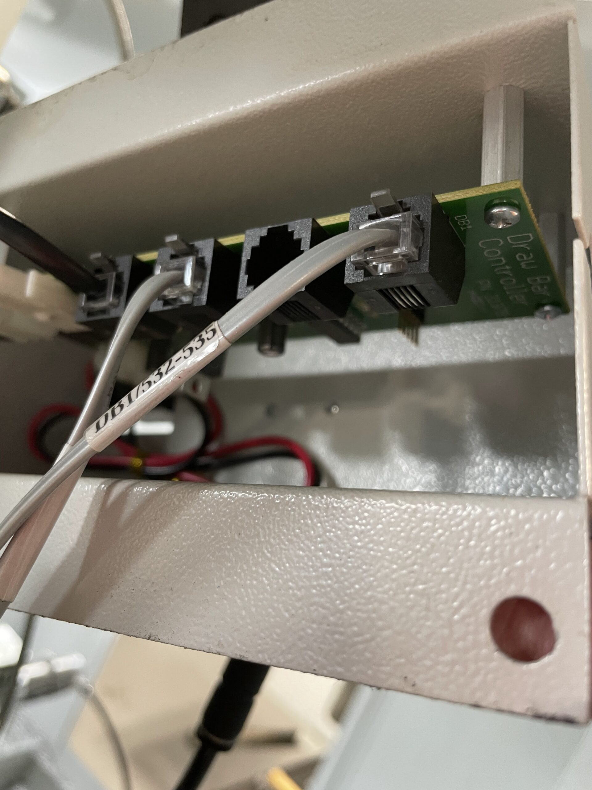
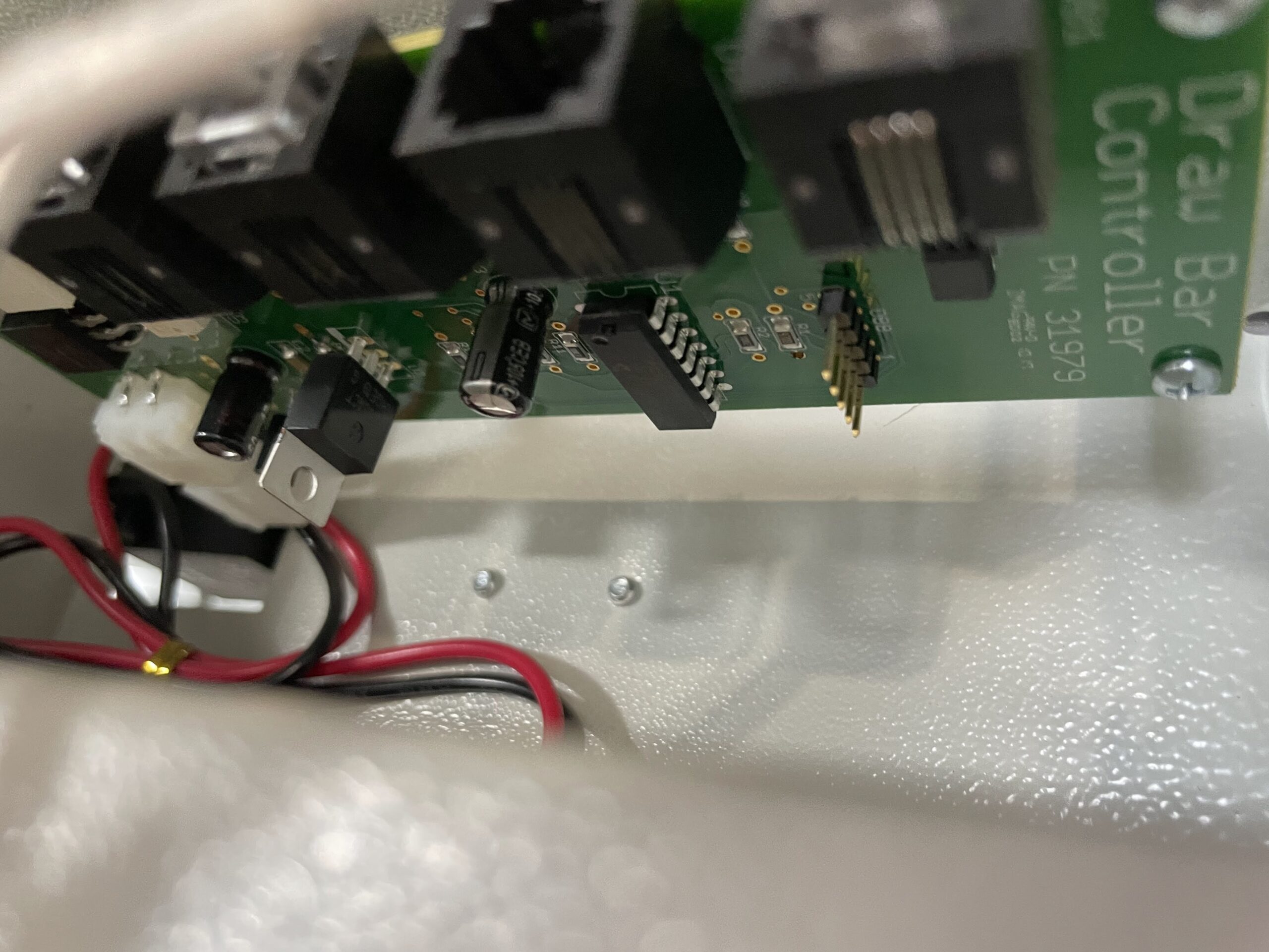
I believe it was Tuesday when I reported having some issue with my Tormach. You can read about the initial symptoms here. Fortunately, Tormach has very good support, at least in my opinion. I had also let Tormach know the automatic draw bar was not functioning, the lock and release buttons were not doing anything despite having good air pressure, and other air pressure related functions working properly. This led them to believe that the draw bar control board may not be receiving power, which would then affect the ATC, as both are used together during tool changes.
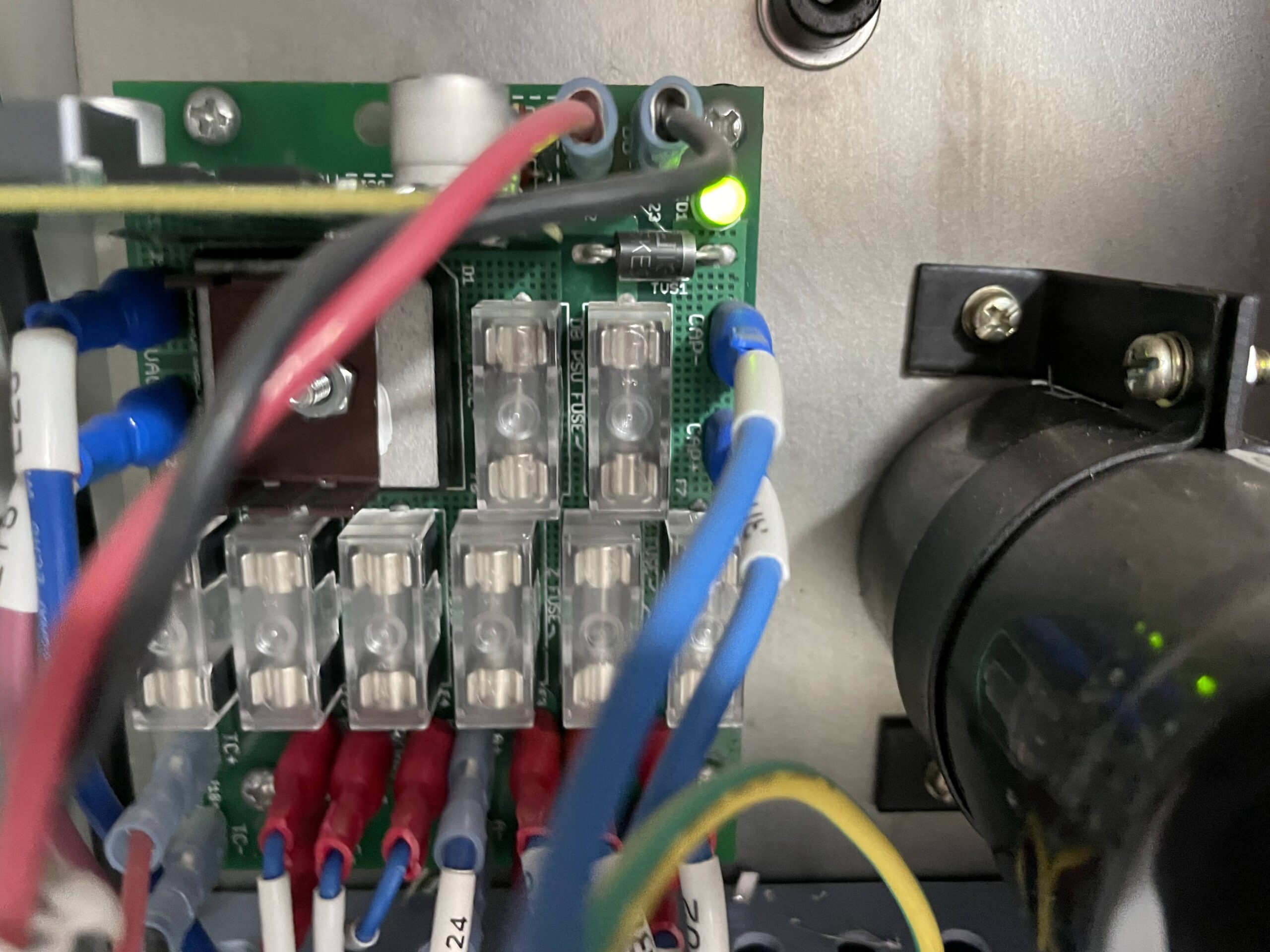
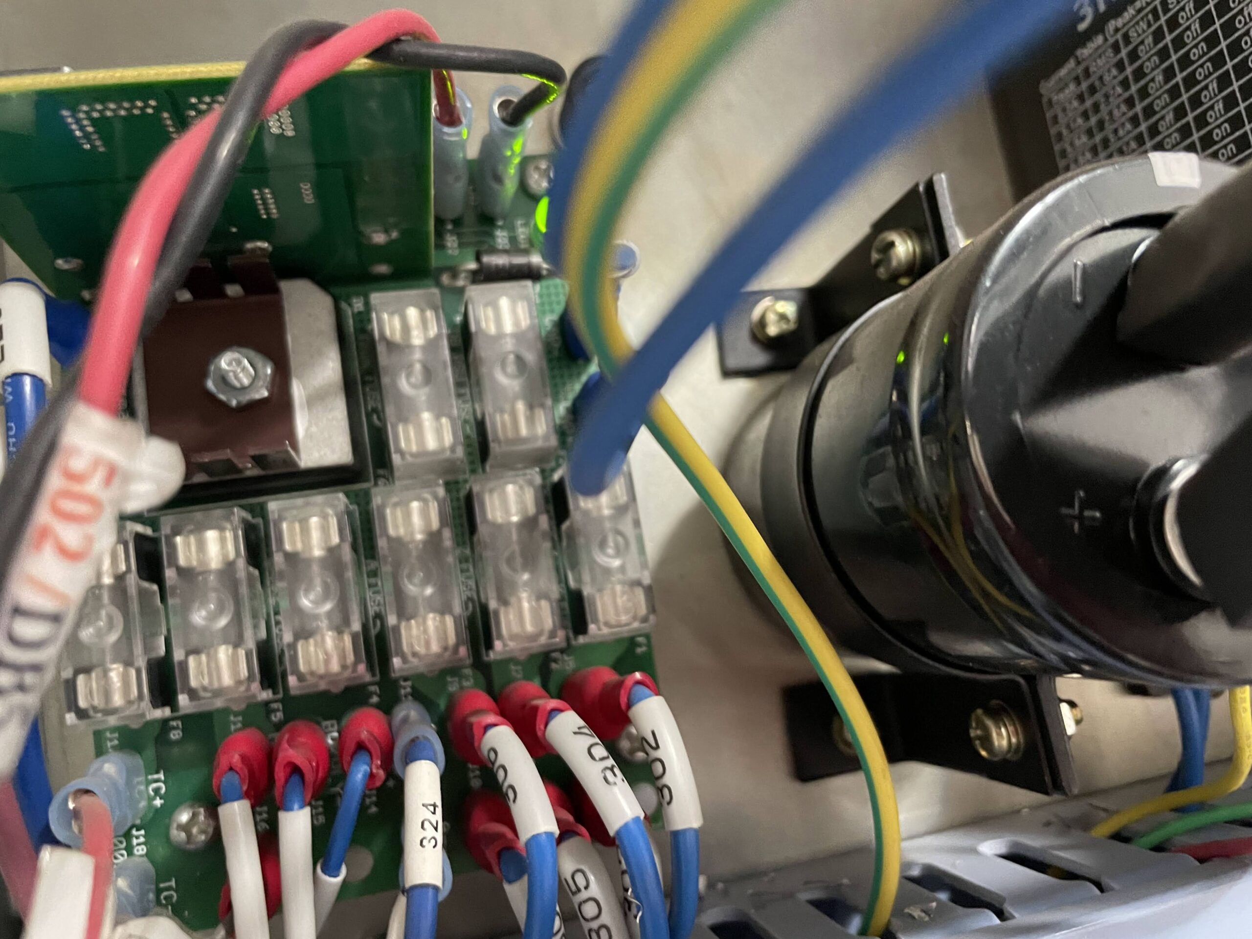
I put a multimeter on the draw bar control board and was not reading any voltage. I traced the wires back to their source at the electrical cabinet and also received not voltage at that point, which suggested perhaps a fuse had blown. However, while looking at the fuse board in the electrical cabinet I did notice a few small chips of aluminum on the board, which might be shorting out the board and causing the issue. I brushed those chips away and retested the wires numbered 501 and 502. 11.92 V showing on the multimeter, problem solved.
Looks like some chips somehow made it into the electrical cabinet and shorted out the fuse board, specifically the 501 and 502 wires to the draw bar control board. It took a day or so to track down the issue, but luckily it was an easy and cheap fix. Some photos below.
Today I was going to perform some test taps on the Tormach mill to make sure I had my speeds and feeds correct. Unfortunately, when I turned on the machine this morning, the computer screen said No Signal and I could hear rapid beeping coming from the computer underneath the mill. I contacted Tormach and they suggested reseating the memory card in the computer. Seemed strange, but they had a pdf guide on how to do it, which suggested its not an uncommon problem. These machines do vibrate a lot, it is certainly a possibility. After reseating the memory card the computer started up without issue. Problem solved.
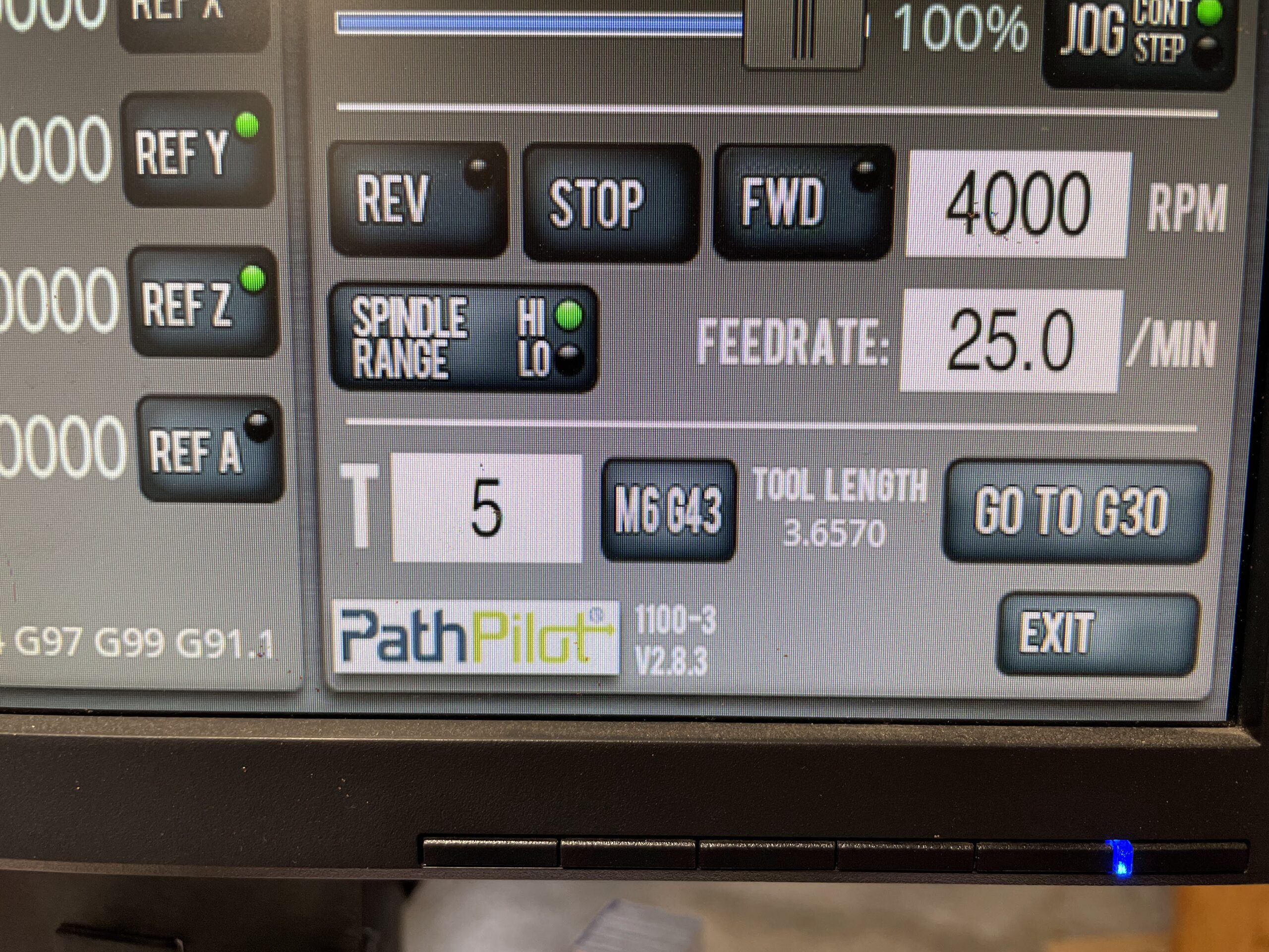
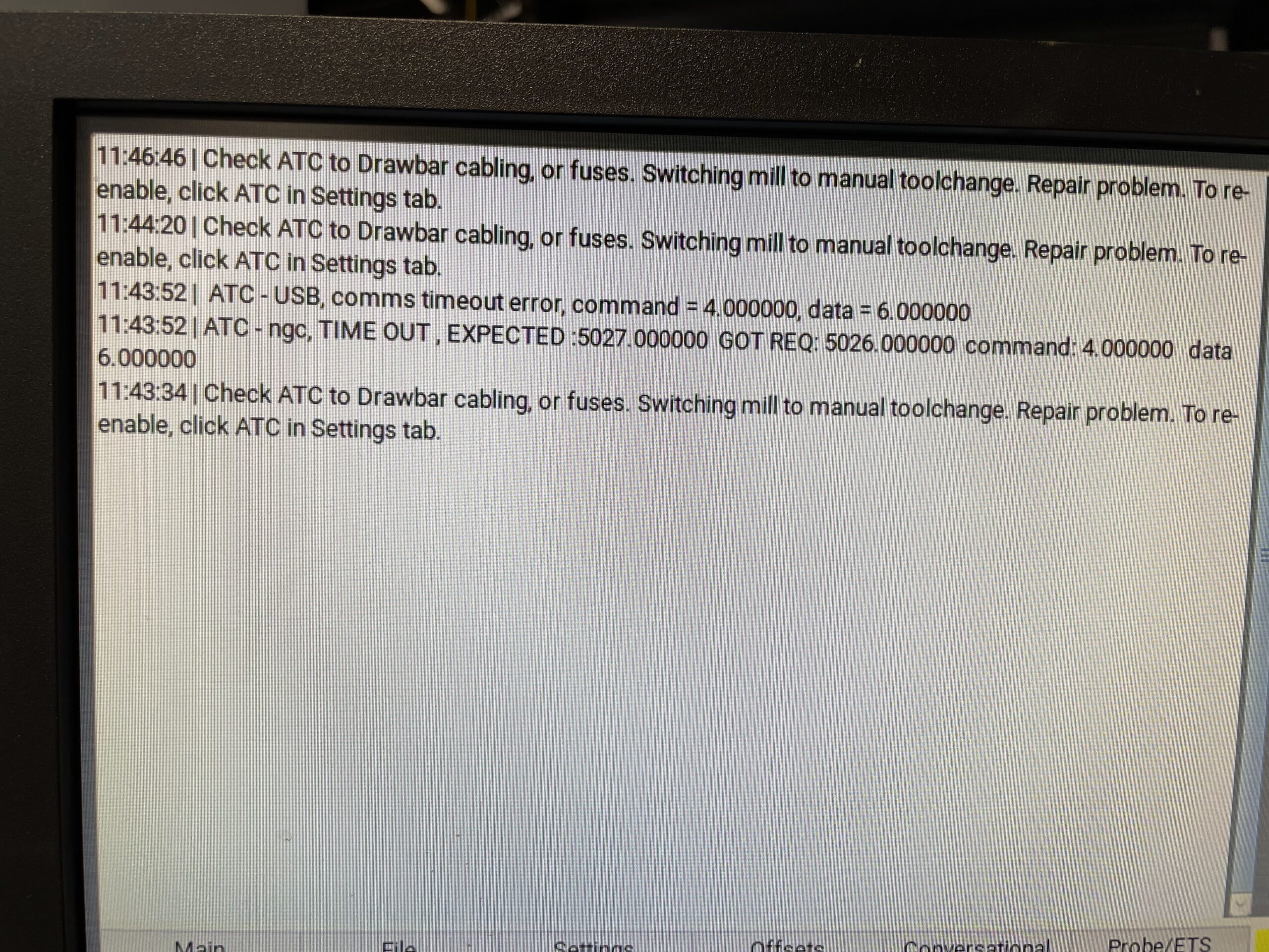
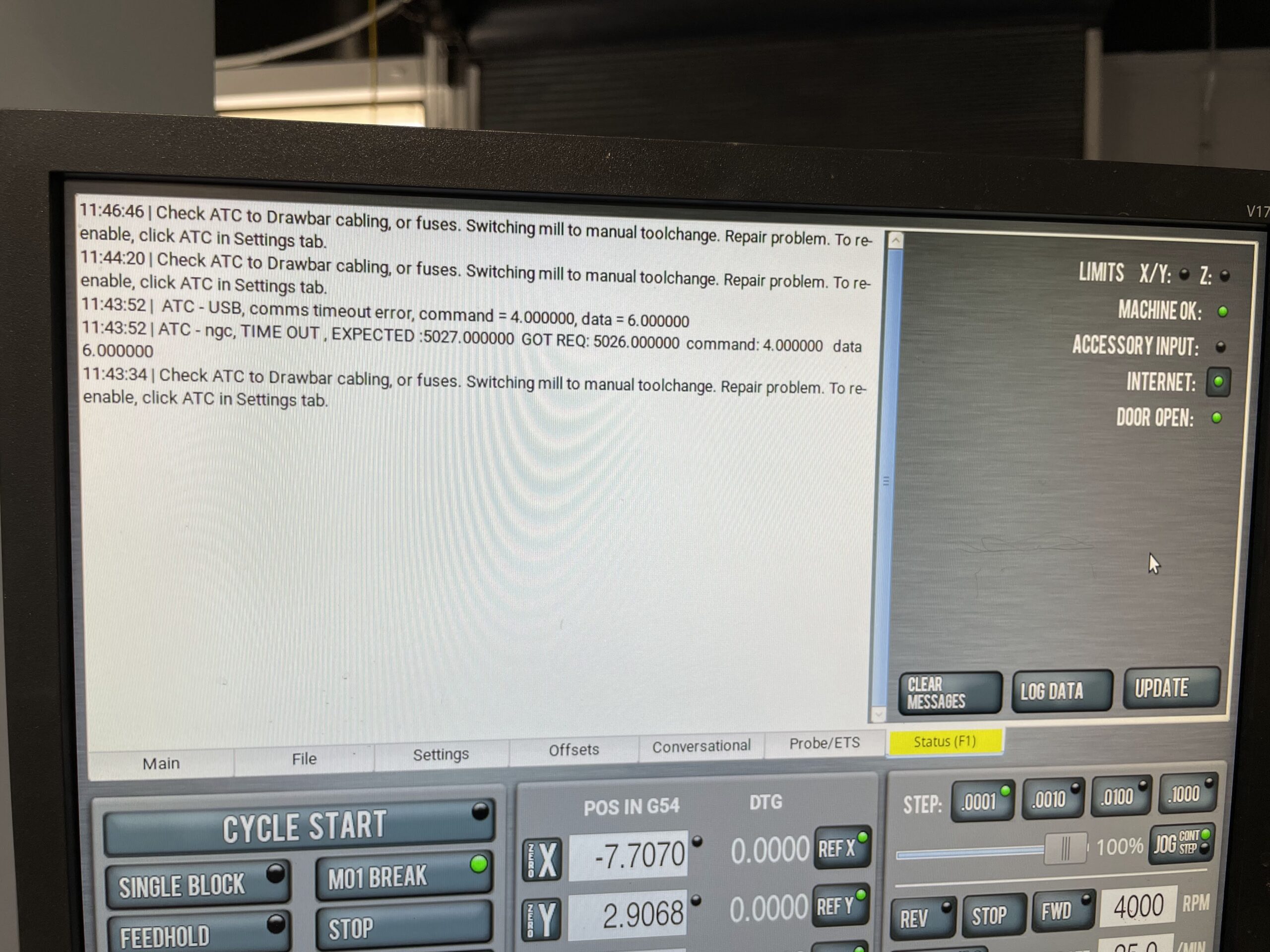
Unfortunately, when trying to use the ATC (Automatic Tool Changer), I received a communication error between the ATC and Draw Bar. They error message said to check the ATC to Drawbar cabling and fuses – but I am not really sure where to start for that. I’ve contacted Tormach again and awaiting their response. They have always been good about getting back to me for support issues, so hopefully we can resolve this quickly. I’ll post some photos of the errors I was receiving.
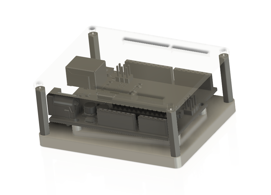
Today I started milling a part that will become a student project. The idea is to have each student learn how to mill their own Arduino holder. The holder allows for easy prototyping, and will give them hands on knowledge of how to use CAD and CAM to to setup a part.
The CAD aspect of the project utilizes a spec sheet in order to get mounting hole dimensions for the Arduino. Students will learn how to import a canvas into Fusion 360 and calibrate the canvas to the correct size. Next, students can build their holder directly on the canvas. Additionally, the CAD project requires importing components from McMaster Carr, and then using the CAM features of Fusion 360 to create the tool paths on two sides of the part. Lastly, the holder requires a laser cut top. Here is an image of the project below.
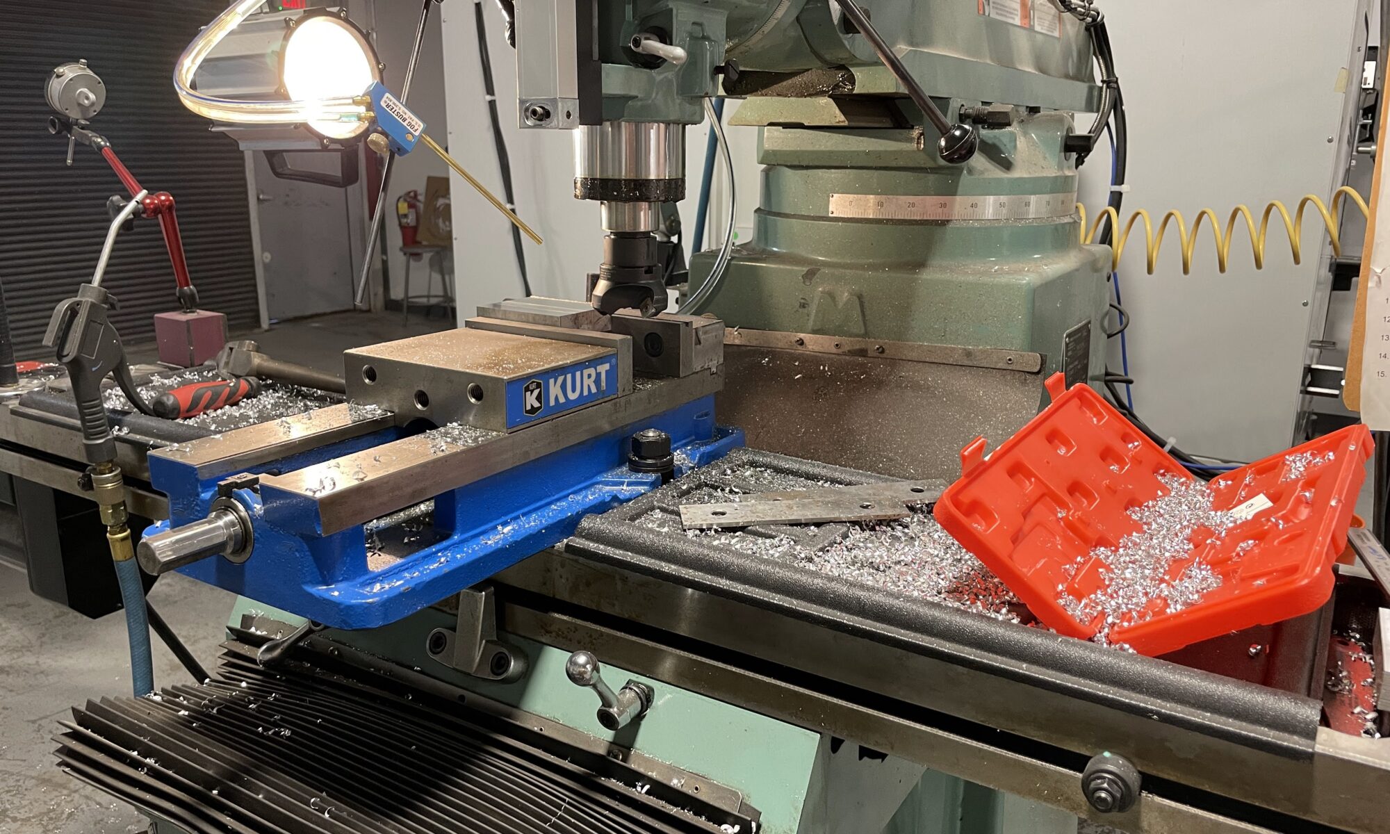
I was able to setup the CAM today and began cutting stock to size. This process started with making 3 cuts on our vertical bandsaw to a large piece of aluminum stock and then placing the stock on our Trax mill to get more precise with the stock dimensions. I am looking for a stock size of 3.2 x 2.6 x 0.8 inches. Below are some images of cutting the stock.
One of my favorite aspects of my job is solving a problem we have never before encountered. Luckily, this happens nearly every day as students are building various types of projects of their own design, such as candy shooters and singing toothbrushes.
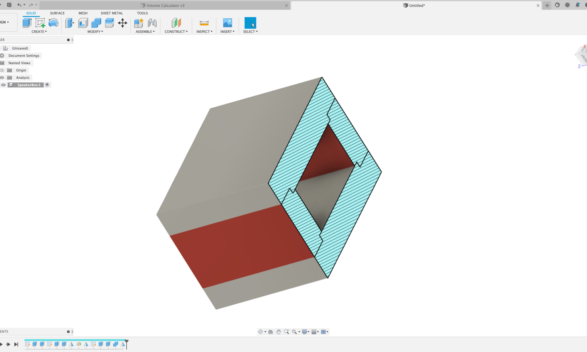
A senior was having problems building a box for a bluetooth speaker setup they were working on, as they were trying to understand how to build the box with the proper volume specified for the speakers he was using. He was taking measurements, putting them into CAD, but when things changed within his project, he would have to change all his dimensions again and it was a real tedious task.
Working together we were able to solve the problem using parameters in Fusion 360. We utilize Fusion 360 for all our CAD needs in the classroom. It’s an easy to learn, robust software with built-in CAM that enables us to send our models to all the different machines we have in the shop – 3D printers, waterjet, plasma cutter, mills, lathes, etc. It’s also free software, and I have the ability to setup an educational account and give access to all my students, rather than having each student setup their own personal account. I really like the way they have the new educational account setup for teachers and students, makes life much easier than before where students needed to verify their accounts which was often problematic.
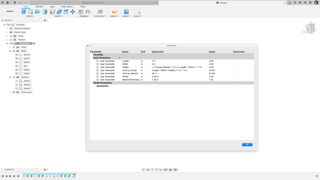
Back to the parameters discussion. By utilizing parameters in Fusion 360 along with an organized modeling strategy, we found a way to control the volume of the box so it always remains constant, even when we change the length, width, or size of material. Below is a screenshot of the parameter setup for the project. You’ll notice some odd math happening, as there are several instances of multiplying 1 in within an expression. This is because Fusion 360 does not have in² or in³ within its parameters framework, so you need to use the 1 in to cancel out parts of an expression so it has the same units Fusion 360 can work with.
I went ahead and created a quick modeling video for students, so in the future I can just point them to the video instead of showing them directly, which frees me up to help other students in our classroom. Video below.