Tormach Resolved

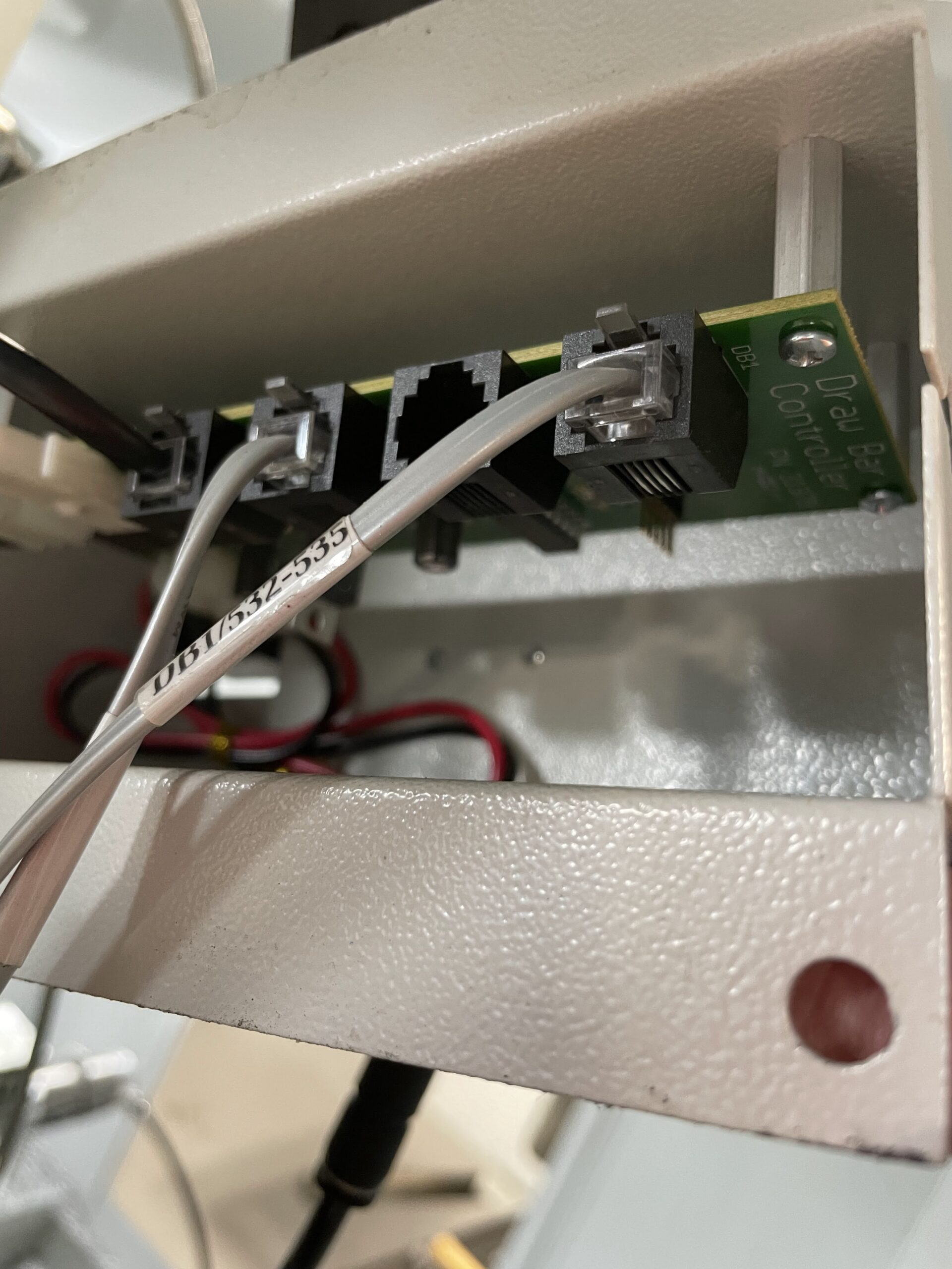
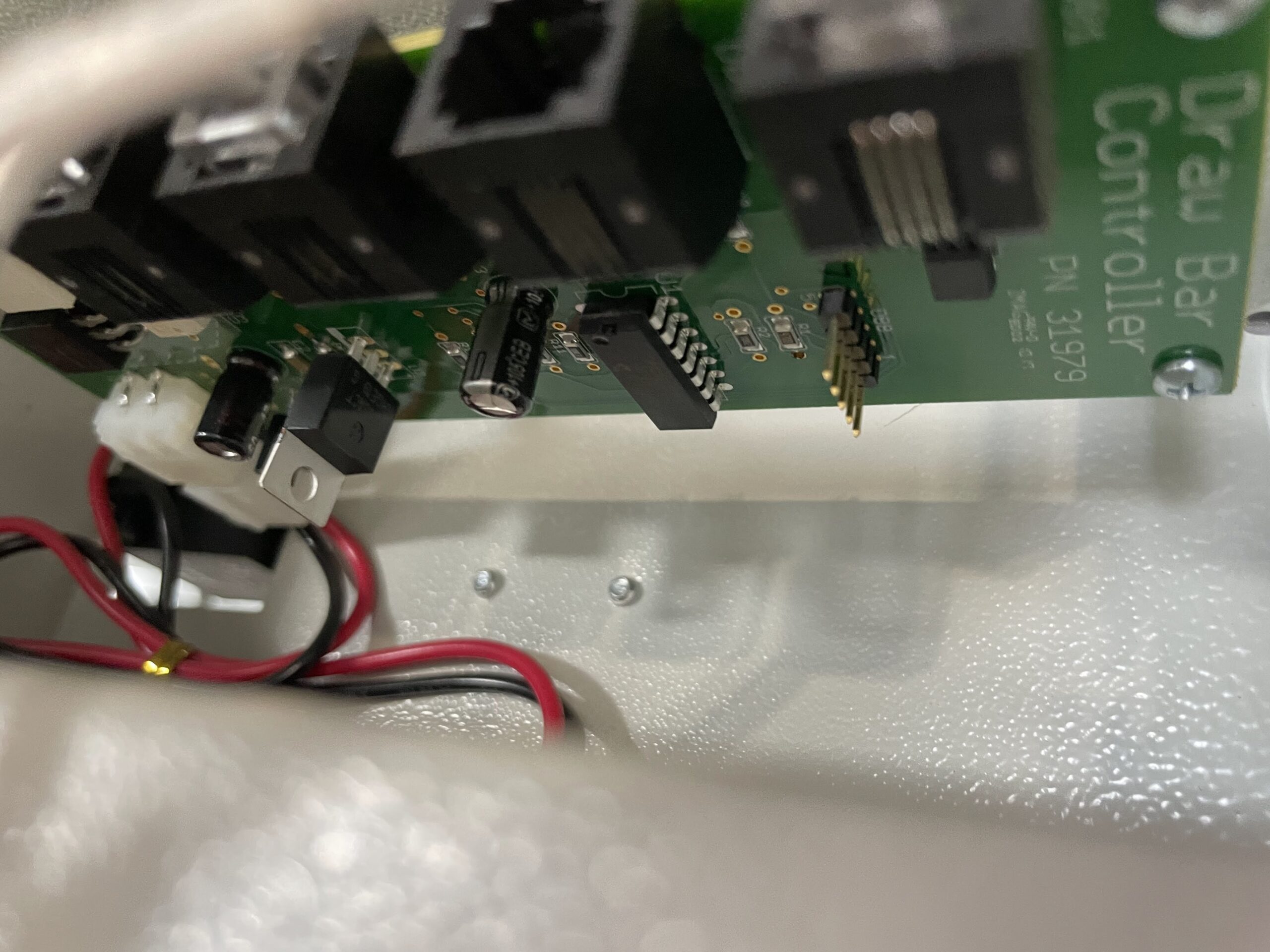
I believe it was Tuesday when I reported having some issue with my Tormach. You can read about the initial symptoms here. Fortunately, Tormach has very good support, at least in my opinion. I had also let Tormach know the automatic draw bar was not functioning, the lock and release buttons were not doing anything despite having good air pressure, and other air pressure related functions working properly. This led them to believe that the draw bar control board may not be receiving power, which would then affect the ATC, as both are used together during tool changes.

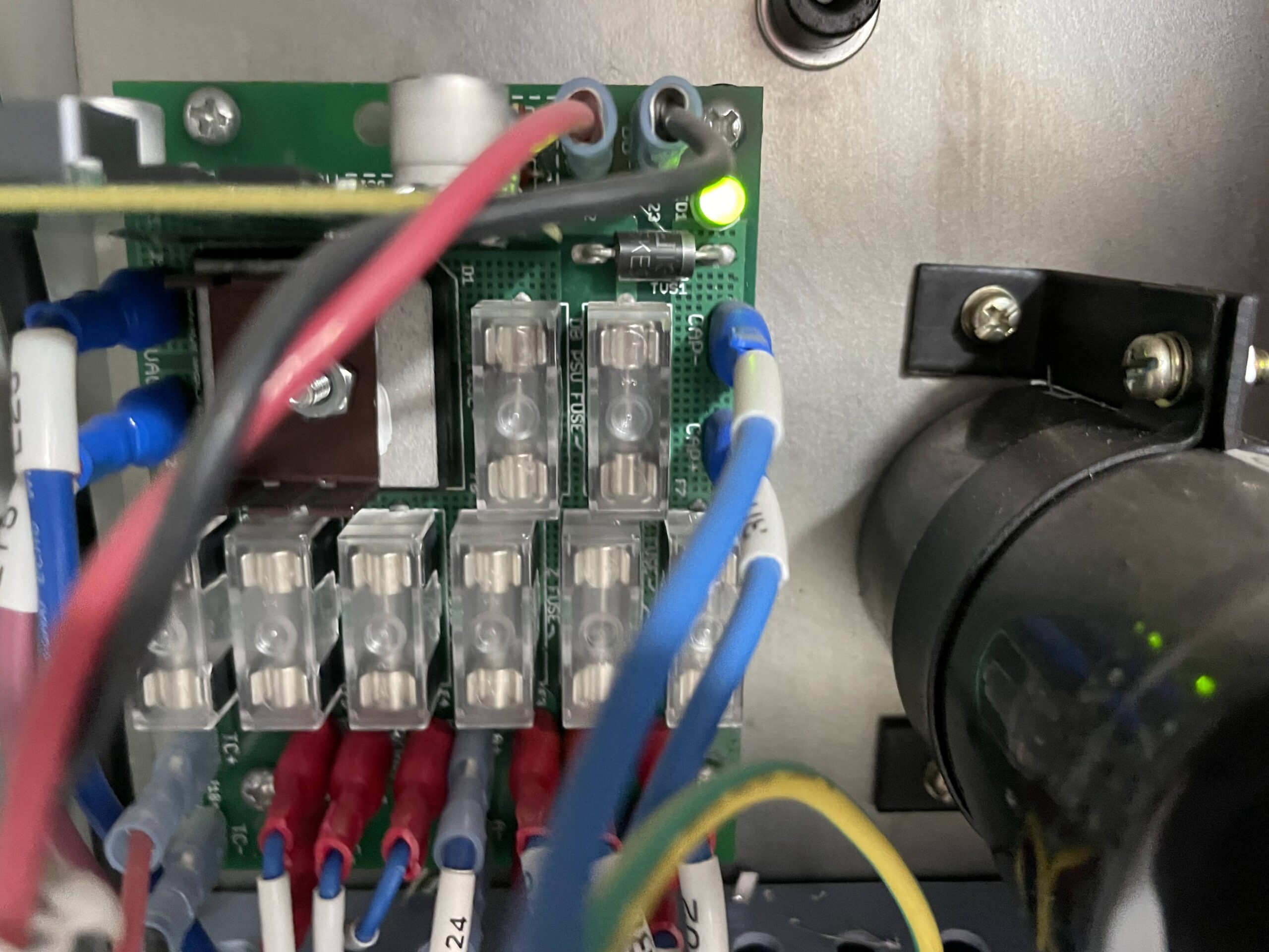
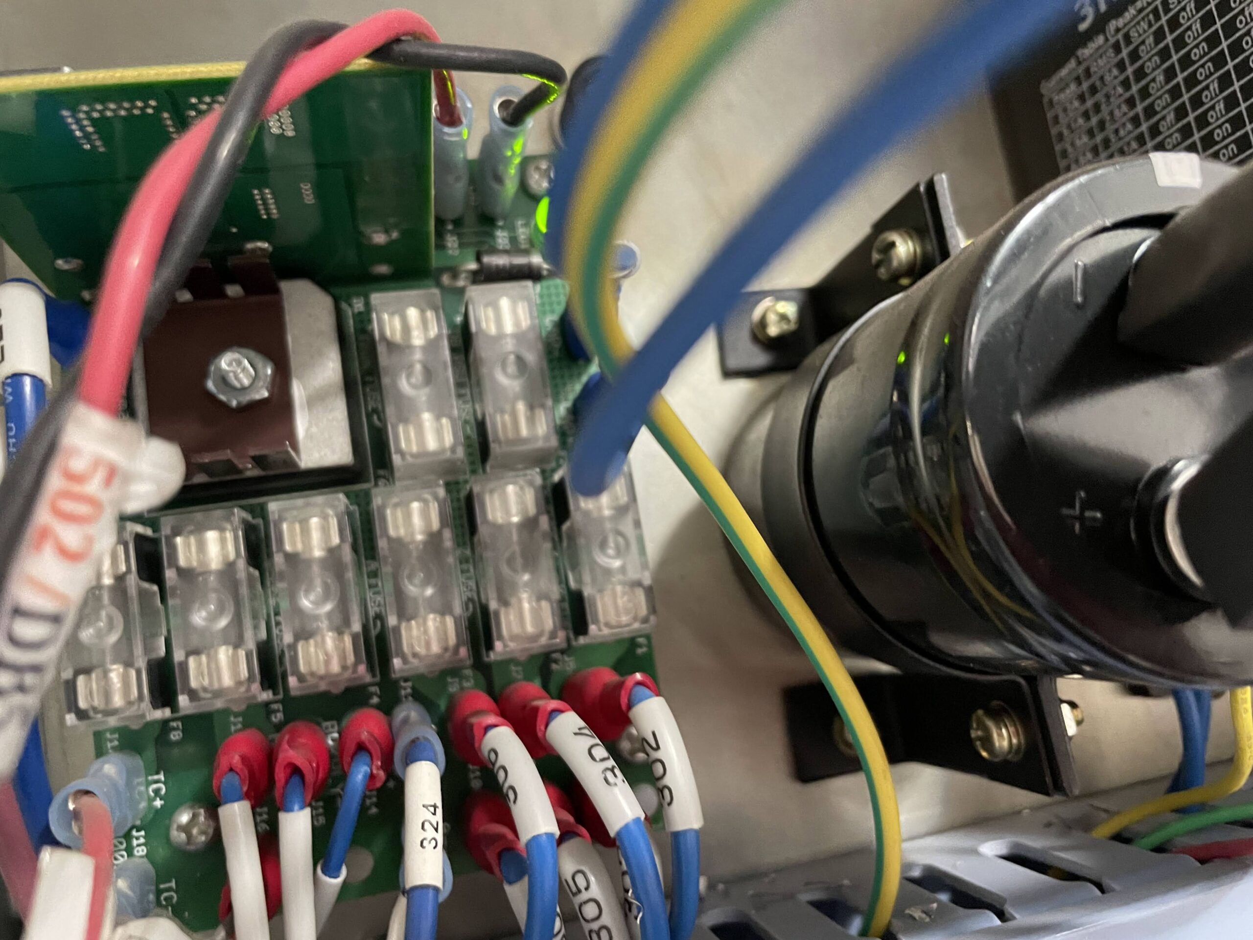
I put a multimeter on the draw bar control board and was not reading any voltage. I traced the wires back to their source at the electrical cabinet and also received not voltage at that point, which suggested perhaps a fuse had blown. However, while looking at the fuse board in the electrical cabinet I did notice a few small chips of aluminum on the board, which might be shorting out the board and causing the issue. I brushed those chips away and retested the wires numbered 501 and 502. 11.92 V showing on the multimeter, problem solved.

Looks like some chips somehow made it into the electrical cabinet and shorted out the fuse board, specifically the 501 and 502 wires to the draw bar control board. It took a day or so to track down the issue, but luckily it was an easy and cheap fix. Some photos below.

Arduino Holder Project

Today I’ll talk a little bit about setting up a part for use on our Tormach PCNC 1100 mill. As I said in a previous post, I’m working on a new project for students, creating a custom arduino holder out of aluminum. I’ve been documenting the process of preparing the stock for the mill.

The project as designed in CAD calls for a 0.8 x 2.6 x 3.2 in block of aluminum stock. I’ve cut a .9″ thick piece of stock from a 6 x 4 inch block and then roughed it to down on the bandsaw to get it close to the dimensions I want. Next, I took it over to our Trax mill and faced off all sides until it was milled to the dimensions mentioned above. I probably do not need to be this precise, but its a good exercise, and will give the students a good beginning in using our manual mills.

Once the block was ready I took it over to our Tormach machine and proceeded to zero out the X, Y, and Z coordinates. This is extremely easy using the Heimer – a measuring tool that provides the zero, or edge, coordinate without the user needing to to any math as might be done with a standard edge finder. See video below.

This project requires a part flip, and for the first attempt, I tried using the same X and Y coordinates – which did not work out. Mostly because the Y coordinates did not match on the flip. Another issue I had was tapping the holes. I did not properly set the RPM and feedrate correctly for the 4-40 tap, and it broke immediately. A silly mistake, but one that will be easily fixed next time I run the job.

There are some photos and videos below of the process, although I forgot to take a photo of the finished product. Will update on the project next week.