Speakers

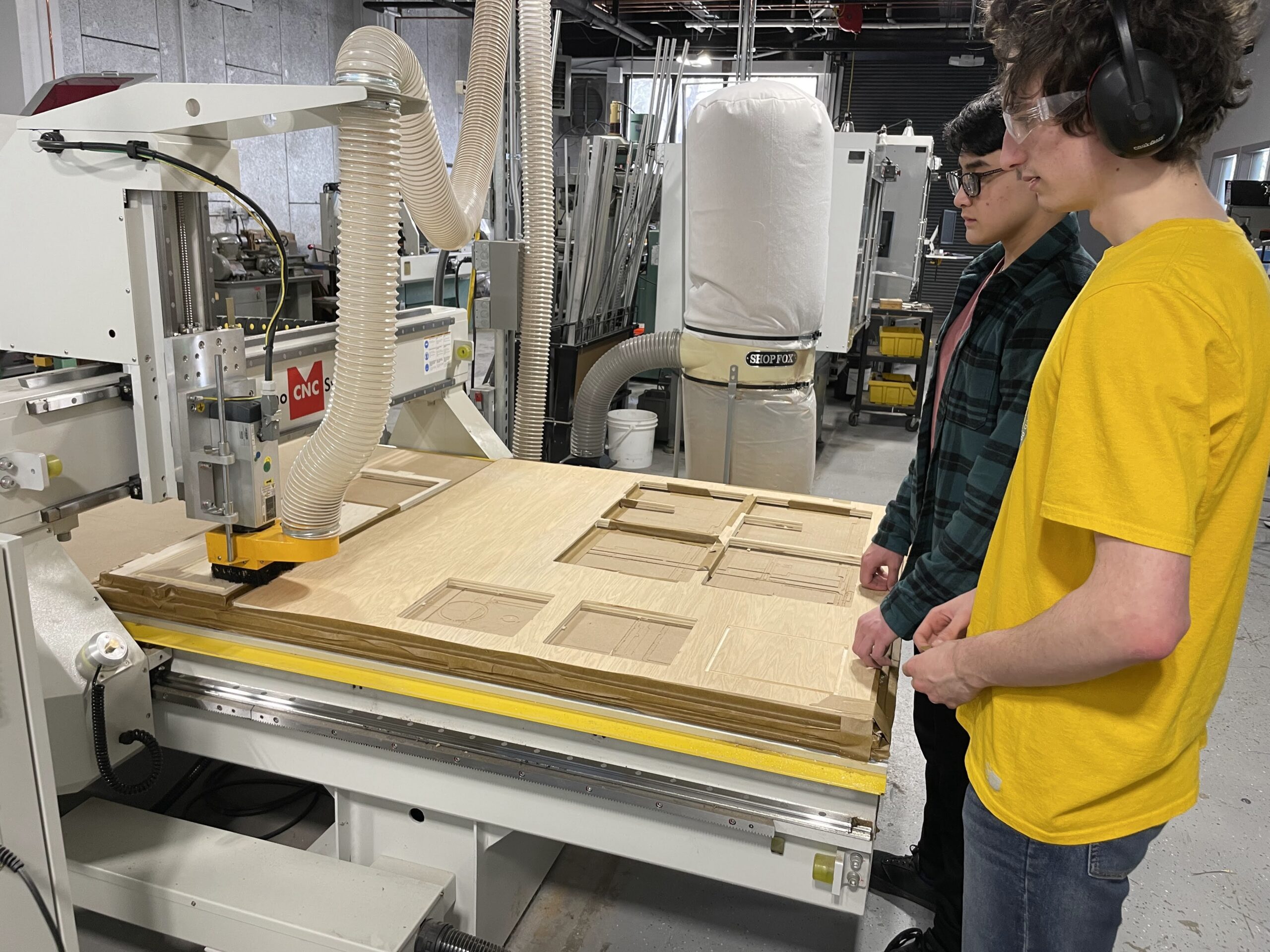
While I’m still getting over the thrill of having a new Tesla to play with, the shop was focused on getting some CNC Router cuts executed today. Seniors Daniel and Lucas have been designing speaker boxes. The boxes are quite particular, using parameters within Fusion 360 to control volume specific to the different speaker dynamics. I wrote about it more specifically earlier this year in this post.

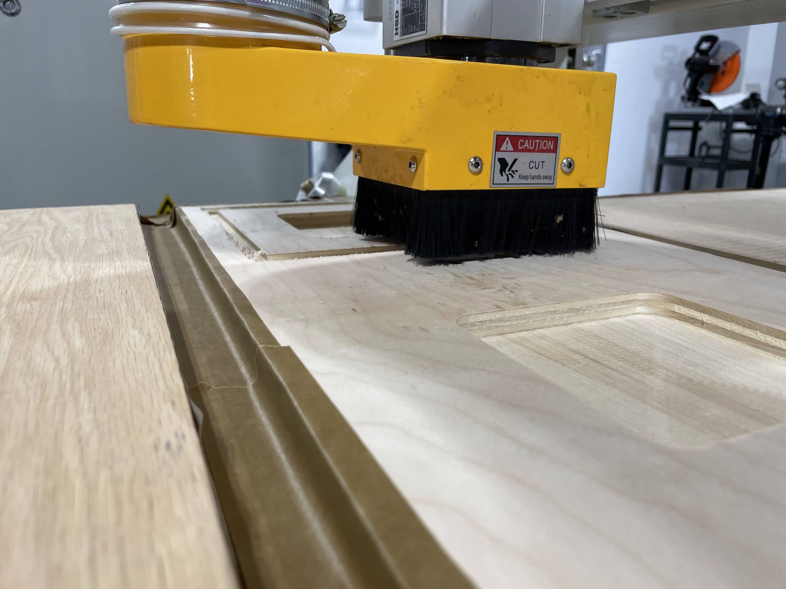
Today we began the first cuts of the Fusion 360 files. We exported the files from Fusion as DXFs and then imported them into VCarve. We created multiple cutting paths for different heights and types (pockets v profiles) and set the Atlas router to work. Below are a few images of the process. We will have more to show next week.

Stop Light

The Stop Light project continues with Junior Clark B. ’23 working fastidiously each day. Clark had the code working on a breadboard, and has spent time using Eagle to create a custom PCB on our Bantam Tools PCB mill. The process of learning how to create a pcb in a CAD/CAM software such as Eagle is very difficult, so kudos to Clark for working through it. As we have found, however, the first attempt at creating a board is usually not the final board – as it tends to take a few efforts before the final working prototype is complete.

When the pcb was coupled together with the relay for high voltage and the light, everything turns on, just now exactly when we want it to. There is probably an error in the code, so Clark needs to spend some time debugging. Still, it’s very close to working properly, ie. following our school schedule, and we have found a stand for it, having repurposed a rolling TV stand that was being thrown away by the Media Tech shop. Hopefully we will be able to present the final version soon. A few in process photos below.

WaterJet

Today one of my senior students, Myles, began cutting a 5 piece metal sign on the waterjet. Myles has taken it upon himself to become an expert in operating our OMAX waterjet. The machine is a bit old, and has some hiccups from time to time, but he has learned how to make it work consistently, and he is getting really good results from his cuts. It’s great to see him excel in working with this machine, and to see him understand the workflow of drawing his designs into CAD, and bringing them over to the OMAX software and setting up the CAM files for cutting. It’s been a long learning process, but he has really learned a lot. A few photos and video of him below operating the machine today.

Pi Radio Internals

Just a quick update on the Pi Radio. I have been working on the internals and am close to having some nice acrylic mounting panels for the interior of the radio. Additionally, I have chosen a speaker to use, which will replace the old damaged speaker that was in the unit when it was purchased. The new speaker is a 4″ Dayton Audio DMA105 8 ohm, which is also being used by another student for a speaker project they are working on. Will post more on that project once it is further along. My radio needs a few more adjustments to the CAD model, and a couple of more test fits before we can wire it up and test my co-teacher’s coding with the Raspberry Pi. A few photos below showing the updated components inside the radio housing.

Tormach Resolved

I believe it was Tuesday when I reported having some issue with my Tormach. You can read about the initial symptoms here. Fortunately, Tormach has very good support, at least in my opinion. I had also let Tormach know the automatic draw bar was not functioning, the lock and release buttons were not doing anything despite having good air pressure, and other air pressure related functions working properly. This led them to believe that the draw bar control board may not be receiving power, which would then affect the ATC, as both are used together during tool changes.

I put a multimeter on the draw bar control board and was not reading any voltage. I traced the wires back to their source at the electrical cabinet and also received not voltage at that point, which suggested perhaps a fuse had blown. However, while looking at the fuse board in the electrical cabinet I did notice a few small chips of aluminum on the board, which might be shorting out the board and causing the issue. I brushed those chips away and retested the wires numbered 501 and 502. 11.92 V showing on the multimeter, problem solved.

Looks like some chips somehow made it into the electrical cabinet and shorted out the fuse board, specifically the 501 and 502 wires to the draw bar control board. It took a day or so to track down the issue, but luckily it was an easy and cheap fix. Some photos below.